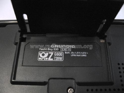
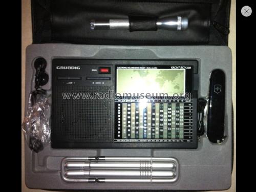
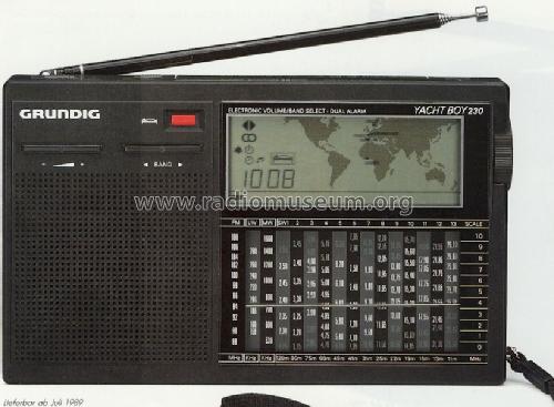
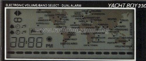
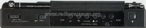
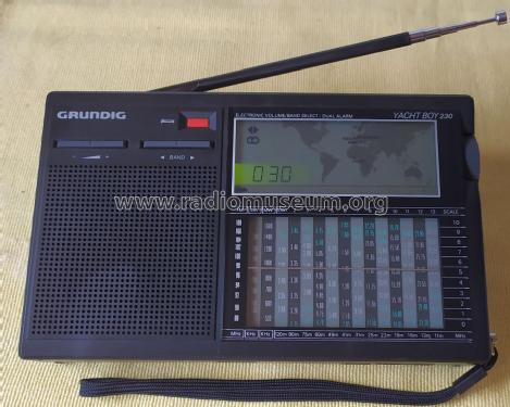
Yacht-Boy 230
Grundig (Radio-Vertrieb, RVF, Radiowerke)
- País
- Alemania
- Fabricante / Marca
- Grundig (Radio-Vertrieb, RVF, Radiowerke)
- Año
- 1989–1992
- Categoría
- Radio - o Sintonizador pasado WW2
- Radiomuseum.org ID
- 97560
-
- alternative name: Grundig Portugal || Grundig USA / Lextronix

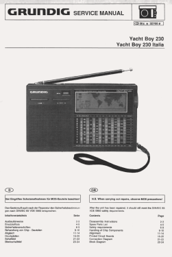


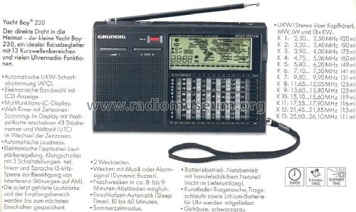
Aus GRUNDIG-Revue 1992.


Radio Dreams
Radio Dreams
Radio Dreams


Haga clic en la miniatura esquemática para solicitarlo como documento gratuito.
- Numero de transistores
- 19
- Semiconductores
- Principio principal
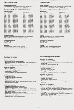
- Superheterodino en general; ZF/IF 455/10700 kHz
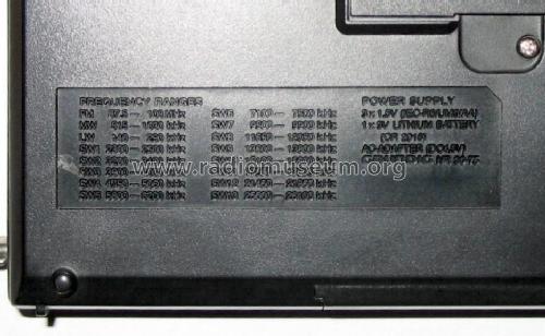
- Gama de ondas
- OM, OL, más de dos OC y FM
- Tensión de funcionamiento
- Pilas + jack (etc.) para alimentación externa. / 3 × 1,5 & 3 / 4,5 Volt
- Altavoz
- Altavoz dinámico (de imán permanente)
- Potencia de salida
- 0.6 W (max.)
- Material
- Plástico moderno (Nunca bakelita o catalina)
- de Radiomuseum.org
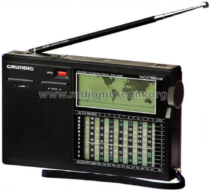
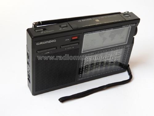
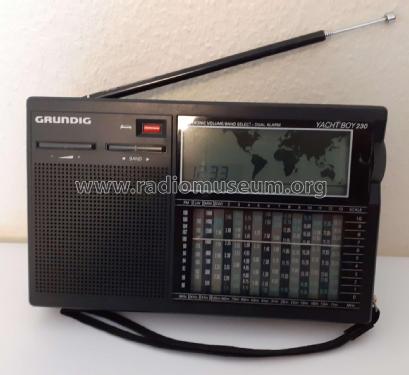
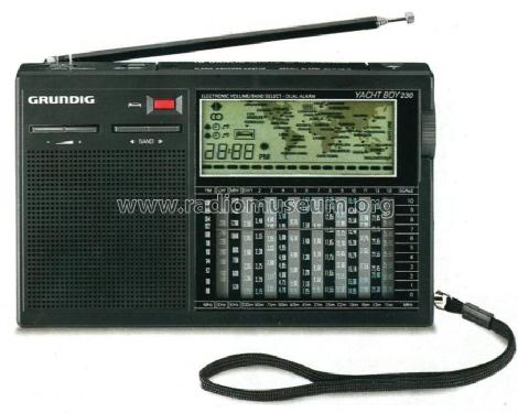
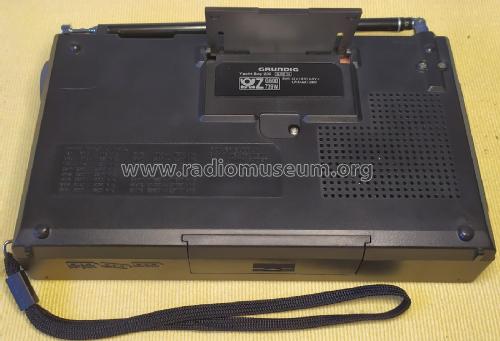
- Modelo: Yacht-Boy 230 - Grundig Radio-Vertrieb, RVF,
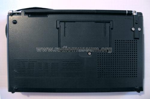
- Forma
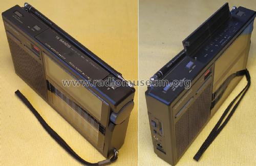
- Portátil de bolsillo , menor de 20cm.
- Ancho, altura, profundidad
- 180 x 109 x 35 mm / 7.1 x 4.3 x 1.4 inch
- Anotaciones
-
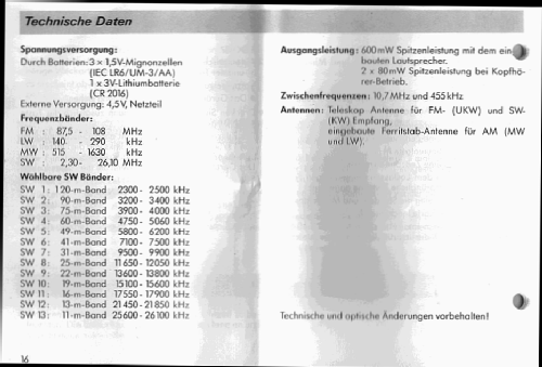
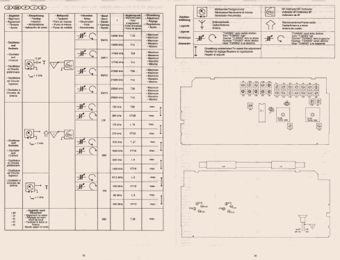
13 KW-Bereiche (11 - 120 m Band), LW, MW, UKW Stereo (mit KH);
LCD - Weltkarte, Uhr, 2 Weckzeiten; Elektronische LS Regelung + Bandwahl, 5kHz Sperre. 6 IC´s . Uhr Knopfzelle: 1×3 V (CR2016), Batterien vom Typ " Mignon ", AC Adapter Grundig 30-75 (4,5 V).Zum Betrieb ist die eingesetzte Knopfzelle erforderlich, ohne funktionsfähige Knopfzelle startet das Gerät nicht.
- Peso neto
- 0.5 kg / 1 lb 1.6 oz (1.101 lb)
- Procedencia de los datos
- -- Original prospect or advert
- Autor
- Modelo creado por un miembro de A. Ver en "Modificar Ficha" los participantes posteriores.
- Otros modelos
-
Donde encontrará 6196 modelos, 5420 con imágenes y 4190 con esquemas.
Ir al listado general de Grundig (Radio-Vertrieb, RVF, Radiowerke)
Colecciones
El modelo Yacht-Boy es parte de las colecciones de los siguientes miembros.
Contribuciones en el Foro acerca de este modelo: Grundig Radio-: Yacht-Boy 230
Hilos: 1 | Mensajes: 1
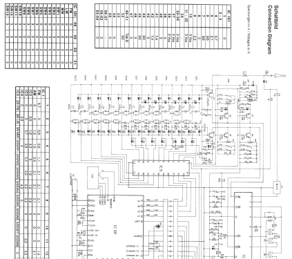
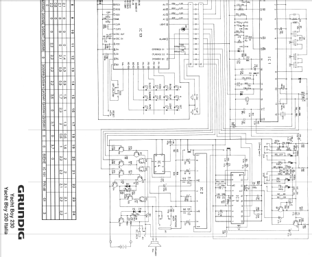
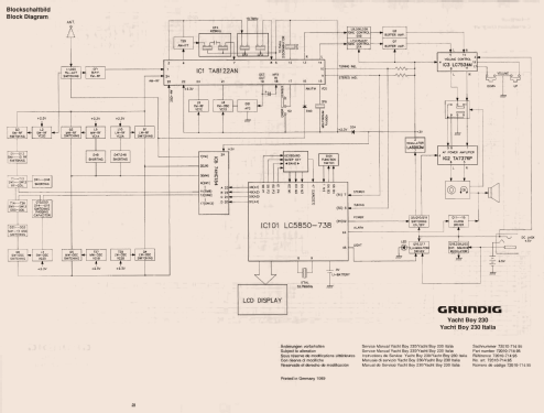
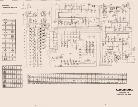
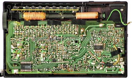
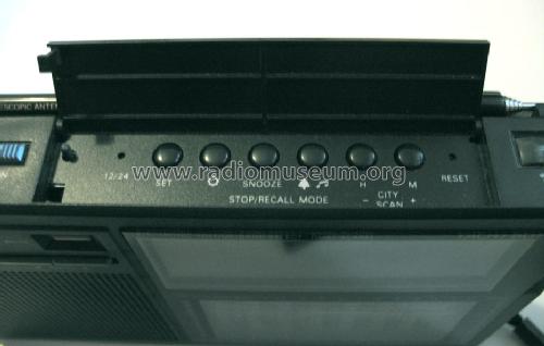
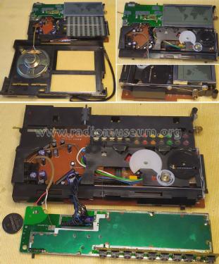
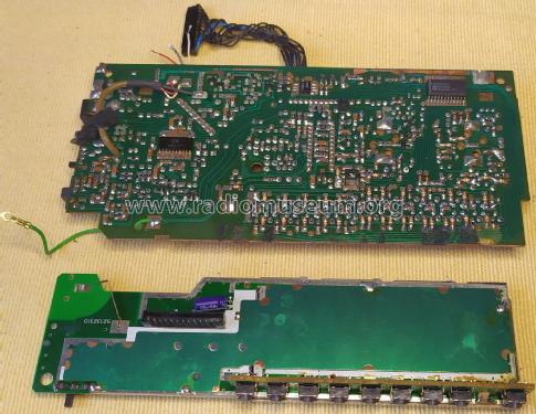
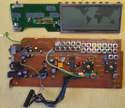
Despite being an analog receiver design, the management is done by a Sanyo LC5850-738 CMOS Single Chip 4-bit Micro-Computer with LCD Driver (IC101 on the PCB), that also supports the Clock, Alarm, Wolrd Map Time Zones, and Sleep functions.
The LC5850-738 receiver management functions are:
- RF Band selection with the help of a 74HC154 4-16 line decoder (IC5) whose output lines enables one of the 16 RF bands available in this radio model.
- Power ON/OFF control. This receiver design do not offer regulated power supply to the Management Processor, therefore the CR2016 3V is the single power source for both Clock and Receiver functions.
- Light control. Neither the Dial Scale nor the LCD feature ilummination, although the offered Light function allows to clearly see the clock time area with a nice green color thanks to the included single green LED (D101).
- Show Tuning and Stereo indicators on the LCD, by reading these signals from the Toshiba TA8122AN AM/FM Tuner IC.
The RF front-end uses discrete active buffer/amplifier devices together with pairs of tuned circuits, one transformer for RF tuning and the other for local oscillator, resulting in the use of a large number of RF transformers and switching devices for RF band selection. This is a good design choice imho.
The filtered RF signal is passed to the Toshiba TA8122AN AM/FM Tuner IC (IC1) that handles the RF amplification, local oscillators and mixers, as well as signal decoding with FM Stereo.
The dual channel audio signal is shaped for Tone Control, actively buffered and then passed to a Sanyo LC7534M Electronic Volume Control (IC3). A Toshiba TA7376P dual channel Audio Power Amplifier (IC2) will drive the stereo earphones while the internal 16 Ohm speaker appears to be connected in bridged mode.
The source of power supply (4.5VDC dry cells, or external adapter) is then used by:
- The IC3 thrugh a transistor switch (Q10)
- The LCD Clock zone green LED thrugh a transistor switch (Q17)
- The Sanyo LA5003M 3V LDO power regulator (IC4) thrugh a transistor switch (Q19).
- The transistor switches are controlled by IC101
- A smart protection circuit, built around a PNP power transistor Q18 is inserted when using a external power adapter.
- The regulated 3VDC from IC4 powers all the remaining devices, where some of them uses a 2.3VDC power source obtained by inserting a series diode (D34) at the output of IC4.
Jose Mesquita, 06.Aug.22