- Country
- United States of America (USA)
- Manufacturer / Brand
- Hallicrafters, The; Chicago, IL and Arlington/Grand Prairie, TX
- Year
- 1948/1949
- Category
- Amateur-Receiver (amateur bands, may include broadcast bands)
- Radiomuseum.org ID
- 43897
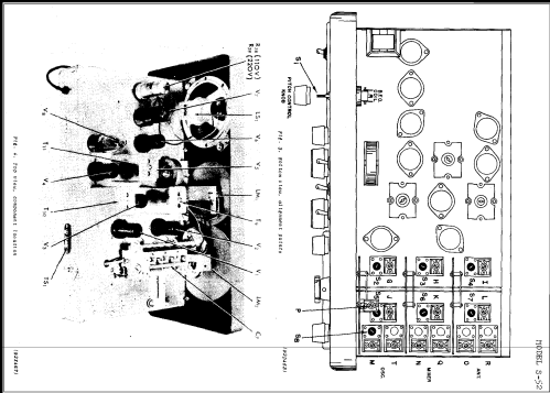
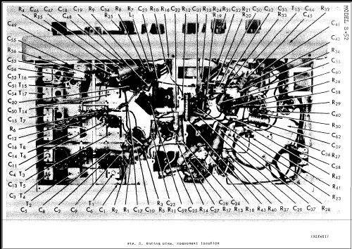


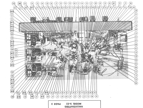


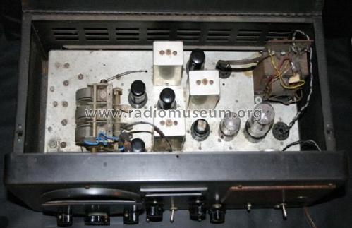

Under chassis view before restoration.
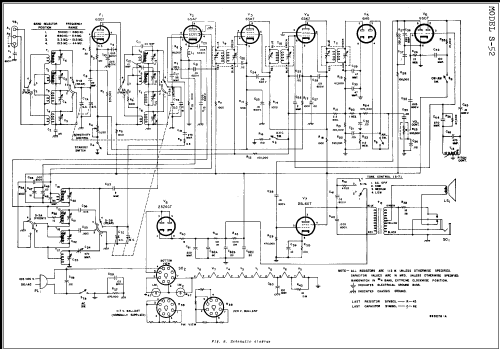
Click on the schematic thumbnail to request the schematic as a free document.
- Number of Tubes
- 8
- Main principle
- Superhet with RF-stage; ZF/IF 455 kHz
- Tuned circuits
- 9 AM circuit(s)
- Wave bands
- Wave Bands given in the notes.
- Power type and voltage
- AC/DC-set / 105-125 or 220 Volt
- Loudspeaker
- Permanent Magnet Dynamic (PDyn) Loudspeaker (moving coil) / Ø 5 inch = 12.7 cm
- Power out
- 2.5 W (unknown quality)
- Material
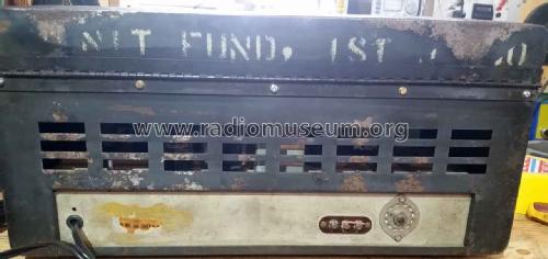
- Metal case
- from Radiomuseum.org
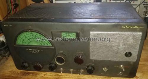
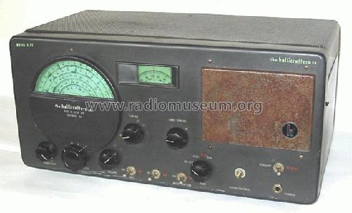
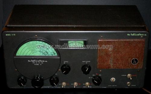
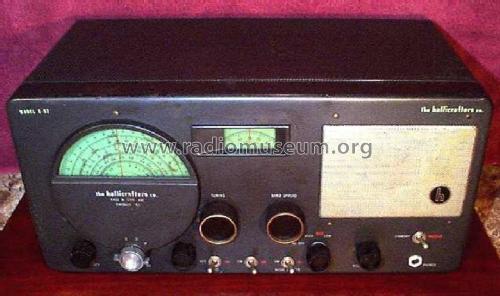
- Model: S-52 - Hallicrafters, The; Chicago,
- Shape
- Tablemodel, low profile (big size).
- Dimensions (WHD)
- 470 x 246 x 210 mm / 18.5 x 9.7 x 8.3 inch
- Notes
-
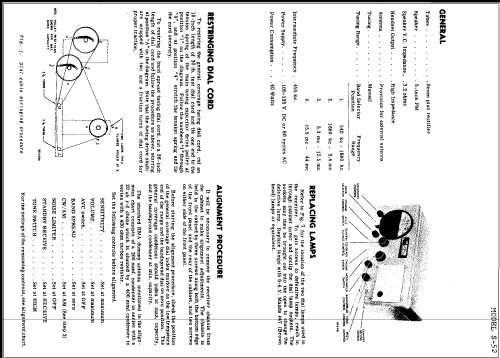
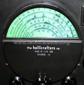
Coverage 0.540-1.68 MHz, 1.68-5.4 MHz, 5.3-15.5 MHz and 15.5-44 MHz. Input voltage change with different ballast tube. Very similar to S-40A.
- Price in first year of sale
- 100.00 $
- External source of data
- Ernst Erb
- Source of data
- Communications Receivers
- Circuit diagram reference
- Rider's Perpetual, Volume 21, Copyright 1950
- Mentioned in
- Shortwave Receivers - Past & Present (3rd ed.)
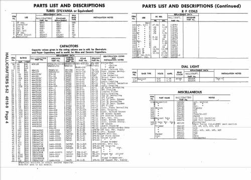
- Literature/Schematics (1)
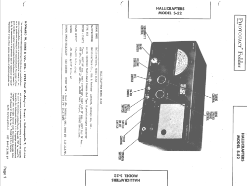
- Photofact Folder, Howard W. SAMS (4818-9)
- Other Models
-
Here you find 898 models, 468 with images and 493 with schematics for wireless sets etc. In French: TSF for Télégraphie sans fil.
All listed radios etc. from Hallicrafters, The; Chicago, IL and Arlington/Grand Prairie, TX
Collections
The model is part of the collections of the following members.
Forum contributions about this model: Hallicrafters, The;: S-52
Threads: 1 | Posts: 6
Gute Tag an die Runde.
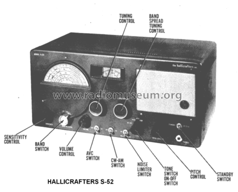
Kann mir jemand von den Schaltungs-Spezialisten die geplante Funktion des Standby-Schalters näher erklären?
Ich kann die Empfindlichkeit bei geschlossenem Schalter (Empfang) verändern, wohl durch Anheben oder Absenken des Potentials der Kathoden der Eingang- und der beiden ZF-Verstärker-Röhren, aber bei offenen Schalter verstärkt das Gerät weiter, ich kann nur nicht mehr regeln. Wo kommt da das Potential der Kathoden her?
Bin für jeden Rat dankbar.
G.Schönbauer

Gerhard Schoenbauer, 24.Jan.21