Micro-Vox (AM transmitter with mike)
Micro-Vox, Inc.; Chicago 6 (IL)
- Produttore / Marca
- Micro-Vox, Inc.; Chicago 6 (IL)
- Anno
- 1949–1952
- Categoria
- Trasmettitore commerciale (TX non ricetrasmettitore)
- Radiomuseum.org ID
- 182249


Popular Science< April 1949 S.56

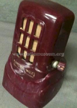
Brown Micro-Vox using 1U4 tube.
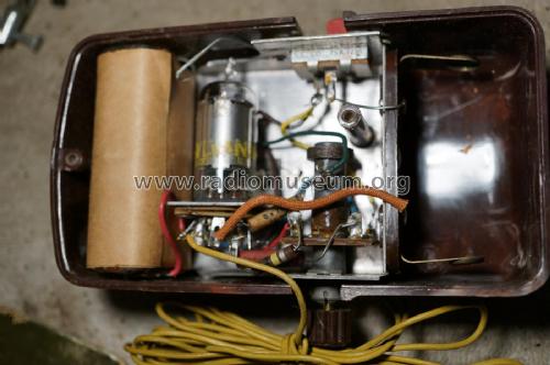
Inside with original B battery.
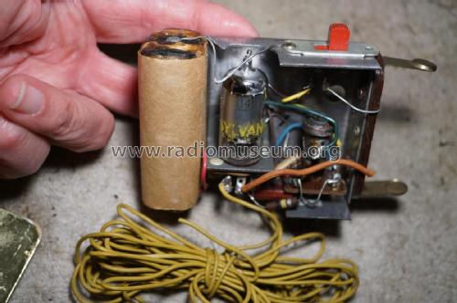
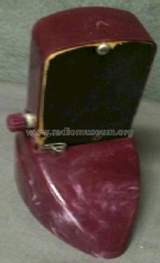
Chassis removed from case.

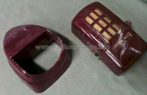
Micro-Vox microphone.
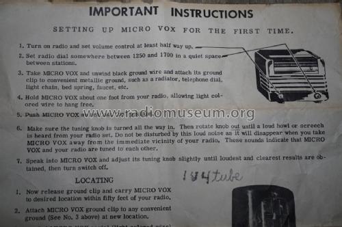
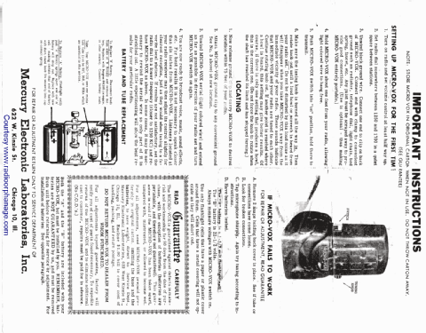
Instruction sheet, top half.

Instruction sheet, bottom half.
Clicca sulla miniatura dello schema per richiederlo come documento gratuito.
- Numero di tubi
- 1
- Principio generale
- Trasmettitore
- N. di circuiti accordati
- 1 Circuiti Mod. Freq. (FM)
- Gamme d'onda
- Solo onde medie (OM).
- Tensioni di funzionamento
- Batterie a secco / 22.5 / 1.5 Volt
- Altoparlante
- - - Nessuna uscita audio.
- Materiali
- Plastica o bachelite
- Radiomuseum.org
- Modello: Micro-Vox - Micro-Vox, Inc.; Chicago 6 IL
- Forma
- Soprammobile con qualsiasi forma (non saputo).
- Dimensioni (LxAxP)
- 3 x 5.5 x 2 inch / 76 x 140 x 51 mm
- Annotazioni
- Micro-Vox;
Pocket sized portable hand-held AM transmitter with microphone, wireless remote microphone in conjunction with any AM radio, range up to 75 feet, table base stand, tuning and on/off switch.
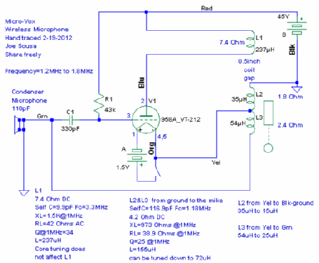
Price start with US$ 7,- and increased up to US$ 9,- in 1952. This wireless microphone was designed for reception in the AM band. However, the modulation method is FM, not AM. The condenser microphone has a measured capacitance around 110pF and imparts the FM modulation directly to the tank circuit. The AM radio then detects the transmitted sound with slope detection. One unit showed a tuning range from 1.2MHz to 1.8MHz under control of the tuning slug in the main resonant tapped inductor.
- Prezzo nel primo anno
- 6.95 $
- Bibliografia
- Advert in US mag. >Popular Science< April 1949 S.56. & >Popular Mechanics< January 1952 S.493
- Autore
- Modello inviato da un iscritto da A. Utilizzare "Proponi modifica" per inviare ulteriori dati.
- Altri modelli
-
In questo link sono elencati 1 modelli, di cui 1 con immagini e 1 con schemi.
Elenco delle radio e altri apparecchi della Micro-Vox, Inc.; Chicago 6 (IL)
Collezioni
Il modello Micro-Vox (AM transmitter with mike) fa parte delle collezioni dei seguenti membri.
Discussioni nel forum su questo modello: Micro-Vox, Inc.;: Micro-Vox
Argomenti: 1 | Articoli: 1
Fellow Radiophiles:
This past weekend I bought a Micro-Vox wireless microphone for $50USD at "Radio XLIII" in Westford Massachusetts USA from Bruce, the owner of RadioOrphanage. Bruce was kind to send me the related documentation by mail.
This little Wireless transmitter uses a single 958A/VT-212 filamentary Acorn triode. This 1949 design is worthy of note because, although it operates in the Medium Wave AM band, it utilizes a very simple form of FM modulation, which then is detected with slope detection in the AM band receiver. The receiver must be tuned slightly above or slightly below the peak signal point for slope detection.
A condenser microphone with a measured capacitance of 110pF serves as the resonant capacitor for the oscillating tank circuit between the grid and filamentary cathode. The variation of microphone capacitance in response to sound waves imparts the FM modulation directly to the output.
The choice of FM modulation made for an extraordinarily simple design, but the received fidelity depends on the shape of the slopes of the frequency response of the receiver. A very selective superheterodyne receiver with sharp IF skirts may very well distort more than a simpler receiver. In the case of the selective receiver, the speech input can be reduced to lower the FM modulation and thus reduce distortion in the steep IF slopes, while maintaining the detected volume.
This wireless microphone comes with a few feed of wire soldered to the anode of the triode to serve as a short antenna. If an additional high Q tuned circuit, like a tuned ferrite loop-stick or tuned loop, were added to the antenna wire, then the FM modulation could be converted to AM before the signal is received by tuning this additional high Q tuned circuit off-peak. This step is equivalent to the slope modulation that would be part of slope detection in the receiver, but with with this slope modulation at the transmitter, the receiver can now be tuned at center channel by any AM radio.
The output coil at the plate is wired to the short antenna wire, and could serve as the second tuned circuit for FM to AM slope modulation before transmission, if a variable tuning capacitor is added between the antenna wire and ground, and the capacitor is tuned off-peak for slope modulation.
My unit was tunable between 1.4MHz and 1.8MHz. The output circuit could be tuned with a 10-50pF variable capacitor for local FM to AM slope modulation before transmission.
Best regards,
-Joe
Joe Sousa, 22.Feb.12