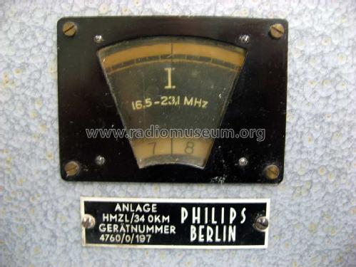
HMZL/34 OKM
Philips Radios - Deutschland
- Country
- Germany
- Manufacturer / Brand
- Philips Radios - Deutschland
- Year
- 1942 ?
- Category
- Commercial Receiver (may include amateur bands)
- Radiomuseum.org ID
- 126300
-
- Brand: Deutsche Philips-Ges.
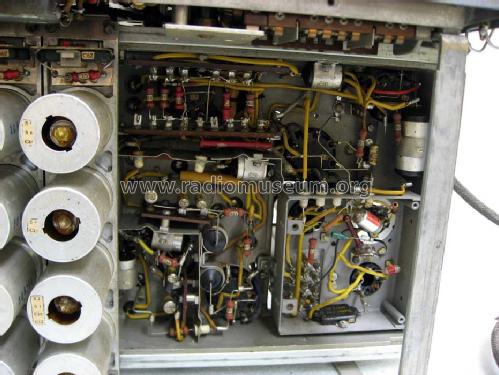
Type & Beschreibung
Größenangaben
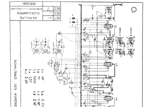
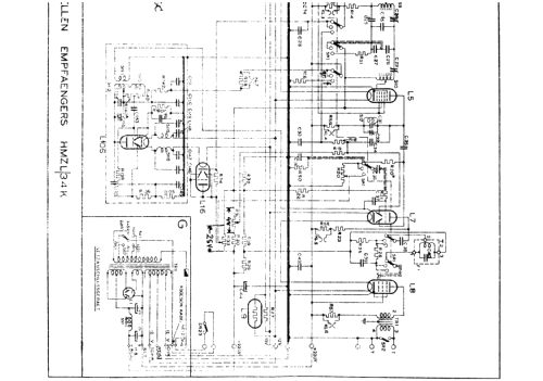
Click on the schematic thumbnail to request the schematic as a free document.
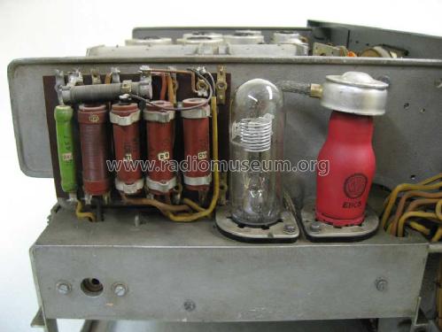
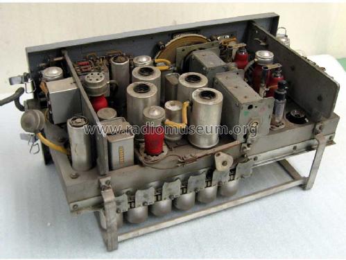
- Number of Tubes
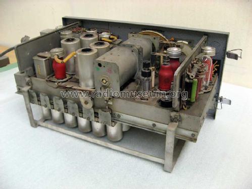
- 9
- Main principle
- Superhet with RF-stage; ZF/IF 280 kHz
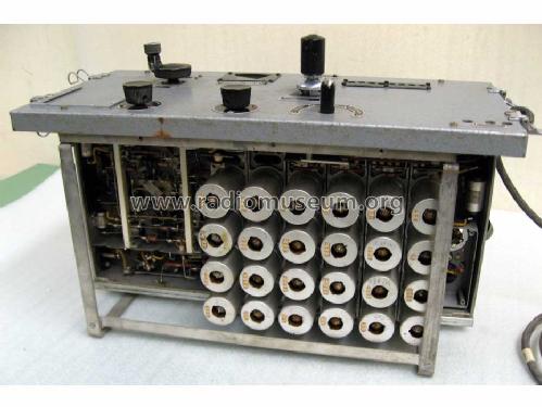
- Tuned circuits
- 8 AM circuit(s)
- Wave bands
- Broadcast plus more than 2 Short Wave bands.
- Power type and voltage
- Alternating Current supply (AC) / 110; 125; 145; 200; 220; 245 Volt
- Loudspeaker
- - For headphones or amp.
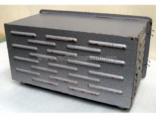
- Material
- Metal case
- from Radiomuseum.org
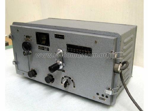
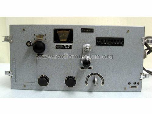
- Model: HMZL/34 OKM - Philips Radios - Deutschland
- Shape
- Boatanchor (heavy military or commercial set >20 kg).
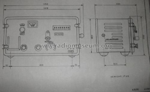
- Dimensions (WHD)
- 517 x 275 x 275 mm / 20.4 x 10.8 x 10.8 inch
- Notes
-
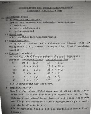
Bereich 1 = 1,50 ... 2,40 MHz
Bereich 2 = 2,40 ... 4,00 MHz
Bereich 3 = 4,00 ... 6,45 MHz
Bereich 4 = 6,45 ... 10,6 MHz
Bereich 5 = 10,6 ... 16,5 MHz
Bereich 6 = 16,5 ... 23,1 MHz
Gewicht gemessen ohne Netzanschlußgerät.Als Netzgerät wurde bei der deutschen Marine z.B. der Typ U.O.R.1 vewendet.
- Net weight (2.2 lb = 1 kg)
- 22 kg / 48 lb 7.3 oz (48.458 lb)
- Literature/Schematics (1)
- -- Original-techn. papers.
- Author
- Model page created by Geert Schulte. See "Data change" for further contributors.
- Other Models
-
Here you find 2540 models, 2252 with images and 1555 with schematics for wireless sets etc. In French: TSF for Télégraphie sans fil.
All listed radios etc. from Philips Radios - Deutschland
Forum contributions about this model: Philips Radios -: HMZL/34 OKM
Threads: 1 | Posts: 2
Dear fellow collectors,
in order to bring my HMZL back to working condition, I need documentation for the U.O.R.1 universal power supply. It's an impressive device with a big power transformer, two choppers, and a whole lot of chokes and electrolytics. There is a switchboard that allows the unit to be set for a whole range of input power options, A.C. and D.C.
Unfortunately, my unit was not only repaired, but modified along the way. Some caps were replaced, some of the wiring was changed, and some resistors bypassed. I could probably fix it for A.C. operation, but in order to achieve full service for D.C. as well, I need your help. Has anyone got a schematic, or has maybe seen/worked/repaired a unit in original condition?
Your help is appreciated,
Nikolaus Loewe
Nikolaus Löwe, 09.Dec.13