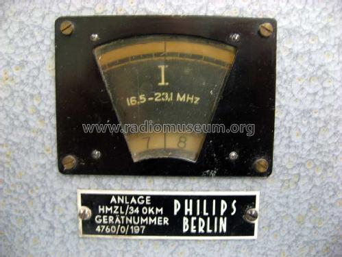
HMZL/34 OKM
Philips Radios - Deutschland
- Hersteller / Marke
- Philips Radios - Deutschland
- Jahr
- 1942 ?
- Kategorie
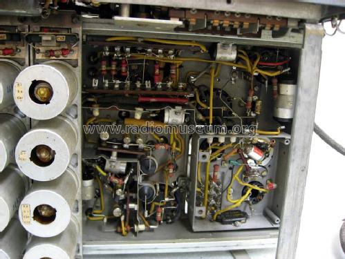
- Kommerzieller Empfänger (auch Amateurbänder)
- Radiomuseum.org ID
- 126300
-
- Marke: Deutsche Philips-Ges.
Type & Beschreibung
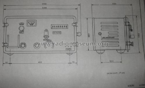
Größenangaben
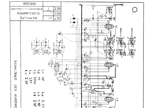
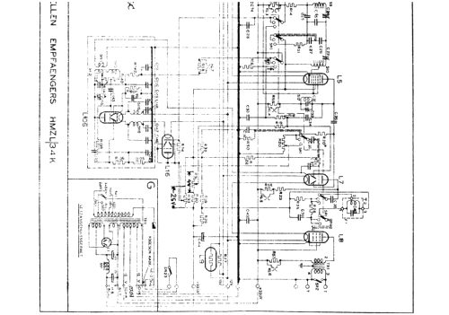
Klicken Sie auf den Schaltplanausschnitt, um diesen kostenlos als Dokument anzufordern.
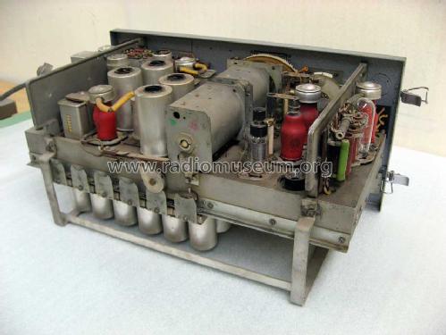
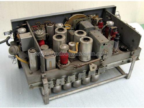
- Anzahl Röhren
- 9
- Hauptprinzip
- Super mit HF-Vorstufe; ZF/IF 280 kHz
- Anzahl Kreise
- 8 Kreis(e) AM
- Wellenbereiche
- Mittelwelle und mehr als 2 x Kurzwelle.
- Betriebsart / Volt
- Wechselstromspeisung / 110; 125; 145; 200; 220; 245 Volt
- Lautsprecher
- - Für Kopfhörer oder NF-Verstärker
- Material
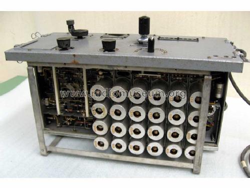
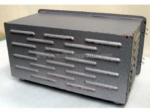
- Metallausführung
- von Radiomuseum.org
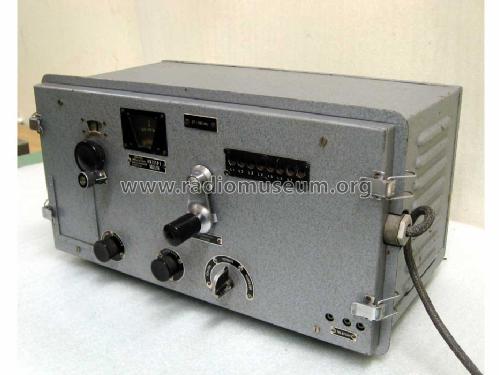
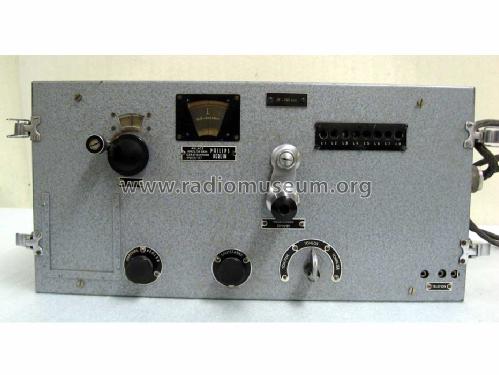
- Modell: HMZL/34 OKM - Philips Radios - Deutschland
- Form
- Schweres Gerät für Militär oder Industrie (Boatanchor > 20 kg).
- Abmessungen (BHT)
- 517 x 275 x 275 mm / 20.4 x 10.8 x 10.8 inch
- Bemerkung
-
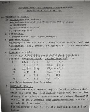
Bereich 1 = 1,50 ... 2,40 MHz
Bereich 2 = 2,40 ... 4,00 MHz
Bereich 3 = 4,00 ... 6,45 MHz
Bereich 4 = 6,45 ... 10,6 MHz
Bereich 5 = 10,6 ... 16,5 MHz
Bereich 6 = 16,5 ... 23,1 MHz
Gewicht gemessen ohne Netzanschlußgerät.Als Netzgerät wurde bei der deutschen Marine z.B. der Typ U.O.R.1 vewendet.
- Nettogewicht
- 22 kg / 48 lb 7.3 oz (48.458 lb)
- Literatur/Schema (1)
- -- Original-techn. papers.
- Autor
- Modellseite von Geert Schulte angelegt. Siehe bei "Änderungsvorschlag" für weitere Mitarbeit.
- Weitere Modelle
-
Hier finden Sie 2540 Modelle, davon 2252 mit Bildern und 1555 mit Schaltbildern.
Alle gelisteten Radios usw. von Philips Radios - Deutschland
Forumsbeiträge zum Modell: Philips Radios -: HMZL/34 OKM
Threads: 1 | Posts: 2
Dear fellow collectors,
in order to bring my HMZL back to working condition, I need documentation for the U.O.R.1 universal power supply. It's an impressive device with a big power transformer, two choppers, and a whole lot of chokes and electrolytics. There is a switchboard that allows the unit to be set for a whole range of input power options, A.C. and D.C.
Unfortunately, my unit was not only repaired, but modified along the way. Some caps were replaced, some of the wiring was changed, and some resistors bypassed. I could probably fix it for A.C. operation, but in order to achieve full service for D.C. as well, I need your help. Has anyone got a schematic, or has maybe seen/worked/repaired a unit in original condition?
Your help is appreciated,
Nikolaus Loewe
Nikolaus Löwe, 09.Dec.13