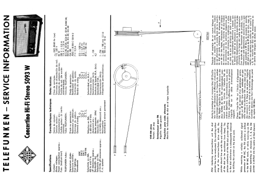
Concertino Hi-Fi Stereo 5093W
Telefunken Deutschland (TFK), (Gesellschaft für drahtlose Telegraphie Telefunken mbH
- Country
- Germany
- Manufacturer / Brand
- Telefunken Deutschland (TFK), (Gesellschaft für drahtlose Telegraphie Telefunken mbH
- Year
- 1959 ?
- Category
- Broadcast Receiver - or past WW2 Tuner
- Radiomuseum.org ID
- 110227

Click on the schematic thumbnail to request the schematic as a free document.
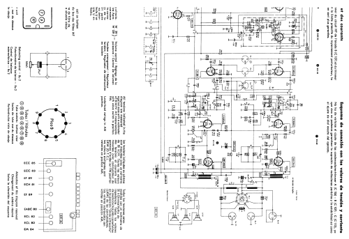
- Number of Tubes
- 9
- Number of Transistors
- Main principle
- Superheterodyne (common); ZF/IF 460/10700 kHz; Export model
- Wave bands
- Broadcast, 2 Short Wave plus FM or UHF.
- Power type and voltage
- Alternating Current supply (AC) / 115; 230 Volt
- Loudspeaker
- 3 Loudspeakers
- Material
- Wooden case
- from Radiomuseum.org
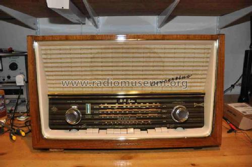
- Model: Concertino Hi-Fi Stereo 5093W - Telefunken Deutschland TFK,
- Shape
- Tablemodel with Push Buttons.
- Dimensions (WHD)
- 24 x 14 x 10.5 inch / 610 x 356 x 267 mm
- Notes
-
Telefunken Concertino Hi-Fi Stereo 5093W (Hi-Fi System) is an export model with MW (515 - 1630 kHz), 2 SW (2.2 - 6.9 MHz and 6.8 - 22.5 MHz), and FM (87.5 - 108 MHz) ranges.
It has 3 loudspeakers: 1 elliptical full range 18 x 26 cm and 2 tweeters Ø 10 cm.
See also the similar model Concertino Hi-Fi Stereo 5093W trop which has "Hi-Fi System" written on the back cover, not on the dial.
- Literature/Schematics (4)
- -- Original-techn. papers.
- Other Models
-
Here you find 3546 models, 3126 with images and 2095 with schematics for wireless sets etc. In French: TSF for Télégraphie sans fil.
All listed radios etc. from Telefunken Deutschland (TFK), (Gesellschaft für drahtlose Telegraphie Telefunken mbH
Collections
The model Concertino Hi-Fi Stereo is part of the collections of the following members.
Forum contributions about this model: Telefunken: Concertino Hi-Fi Stereo 5093W
Threads: 3 | Posts: 10
Hello,
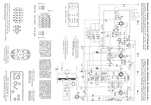
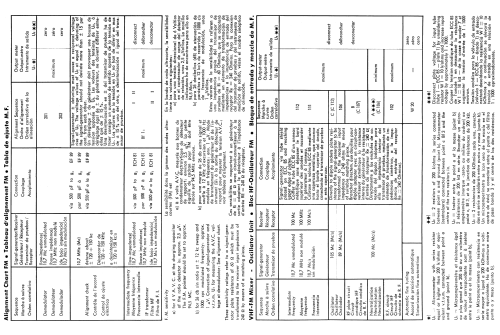
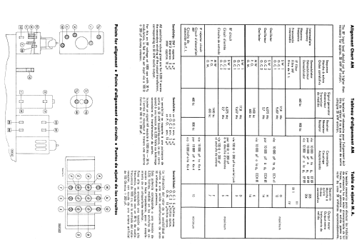
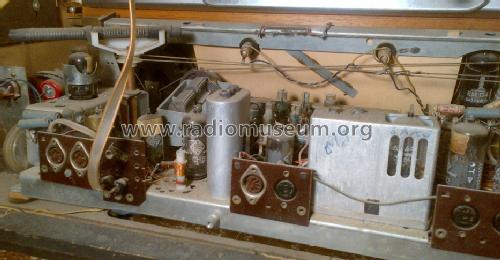
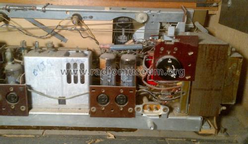
I have an alignment question about this radio. When I received it, the i.f. rejector circuit coil, marked '10' on the alignment point diagram, was not properly connected. I have reconnected it properly, and I want to make sure that it is adjusted correctly, since it appears to have been replaced by a previous owner.
I have completely re-capped the radio. This is the only alignment I want to attempt, since the radio appears to be working correctly, and all of the other coils and capacitors referenced in the alignment documentation are still sealed with the original wax or sealing compound.
The documentation I refer to is attached to this model on the RM website.
In the alignment procedures for the IF rejector circuit, it is stated that the signal generator should be set to 460 khz, radio set at 800 khz, and the signal generator connected to the radio 'via 10000 pF to Ka 4'. I can find no point in the radio schematic or alignment documentation that is labeled 'Ka 4'.
One of the capacitors which can be adjusted is labelled as 'K', but it is also referenced in the alignment 'sequence' documentation as 'K'.
There are two multiposition switches, marked 'K1' and 'K2', one of which uses position 4 on the 'a' side, but it does not seem to make sense to connect to this position with the signal generator for alignment.
Also, where would I connect to measure minimum output for correct alignment? Across the speaker output or audio output transformer?
Any help would be greatly appreciated. As stated before, the radio appears to be working well so I am going to leave it adjusted as it is until I get an answer here.
Thank you, Joe
Joe Brown, 08.Jun.14
Does anyone know how the knobs connect to the indicators? Is it a cord, a rubber band or something else? Gary
Attachments
- telefunken (77 KB)
John Kershaw, 13.Dec.06