- Country
- Germany
- Manufacturer / Brand
- Telefunken Deutschland (TFK), (Gesellschaft für drahtlose Telegraphie Telefunken mbH
- Year
- 1971–1973
- Category
- Broadcast Receiver - or past WW2 Tuner
- Radiomuseum.org ID
- 28363


Telefunken HiFi-Report 1972
Click on the schematic thumbnail to request the schematic as a free document.
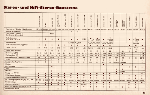
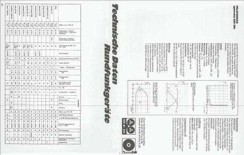
- Number of Transistors
- 28
- Semiconductors
- Main principle
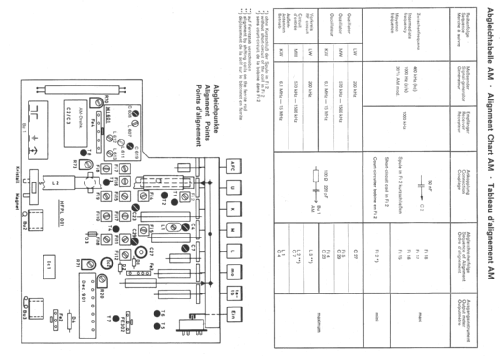
- Superheterodyne (common); ZF/IF 460/10700 kHz
- Tuned circuits
- 6 AM circuit(s) 13 FM circuit(s)
- Wave bands
- Broadcast, Long Wave, Short Wave plus FM or UHF.
- Power type and voltage
- Alternating Current supply (AC) / 110-127; 220-240 Volt
- Loudspeaker
- - This model requires external speaker(s).
- Power out
- 20 W (30 W max.)
- Material
- Wooden case
- from Radiomuseum.org
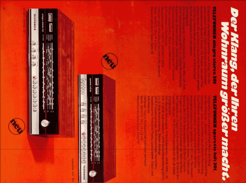
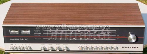
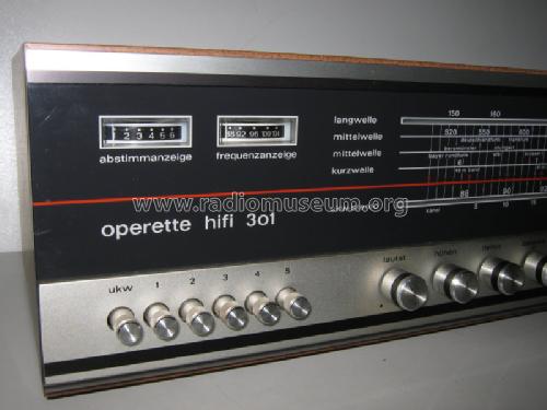
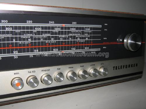
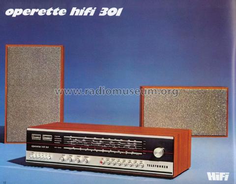
- Model: Operette HiFi 301 - Telefunken Deutschland TFK,
- Shape
- Book-shelf unit.
- Dimensions (WHD)
- 550 x 140 x 220 mm / 21.7 x 5.5 x 8.7 inch
- Notes
- ICs: 1.
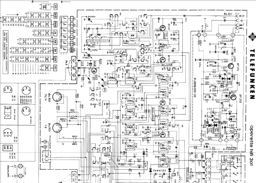
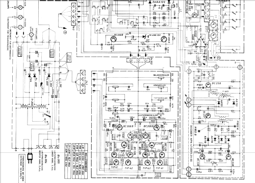
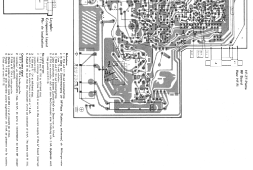
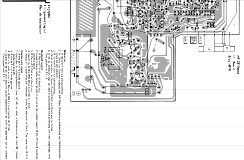
HiFi-Stereo-Steuergerät. NF-Verstärker mit 2 Endstufen je 10 W (Sinus).
- Net weight (2.2 lb = 1 kg)
- 6.3 kg / 13 lb 14 oz (13.877 lb)
- Price in first year of sale
- 398.00 DM
- External source of data
- Erb
- Source of data
- Handbuch VDRG 1971/1972
- Literature/Schematics (1)
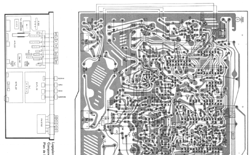
- -- Schematic
- Other Models
-
Here you find 3546 models, 3126 with images and 2095 with schematics for wireless sets etc. In French: TSF for Télégraphie sans fil.
All listed radios etc. from Telefunken Deutschland (TFK), (Gesellschaft für drahtlose Telegraphie Telefunken mbH
Collections
The model Operette HiFi is part of the collections of the following members.
Forum contributions about this model: Telefunken: Operette HiFi 301
Threads: 1 | Posts: 1
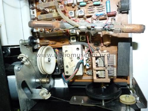
Dear radiofriends
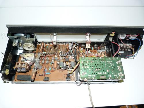
I needed to replace the cord to this radio using the complex diagram and without any instructions that Telefunken has elaborated (d_tfk_operette_hifi301_seil.pdf).
The best most practical process I got was this:
-
In the first step is to get a cord with about 2,5 meters, there will be a bit of cord left, but it is better to spare than after the end of work is missing.
-
The AM variable capacitor is opened, ie at the highest frequency (1600 KHz), and the drum that drives the FM coil and thus to secure the coil core at the highest frequency (104 MHz).
-
Fix one of the ends of the cord with the recommended length on the drum (black) of the variable capacitor AM, in the hole of the knot, keeping the variable always in the same position, wrap the cord with three turn counterclockwise.
-
After passing by the metal roller below, which in turn, the cord will pass through the tuning shaft, in the lower rail giving two turns of cord clockwise.
-
Stretch the cord by following the arrows as shown in figure 1, until the cord enters the drum (white) of FM, wind the cord in the lower rail clockwise with three turns, and the fourth turn will be given in the upper rail of the same FM drum, and through a groove the drum has, passing the cord through the groove continuing to wind in the same direction only one turn of cord then passing the cord through the tuning shaft, in the upper rail giving two turns of cord counter clockwise.
-
Then pass the cord through the plastic roller (with small springs inside), going around it, following the arrows with the cord passing through the small roller of black plastic.
-
Wind the cord through the bottom (clockwise) on the AM drum until it locks into the spring shown in figure 1.
So the cord assembly is finished, with this small contribution I hope to have helped those who in the future encounter the same problem as me.
P.S.
If a member has factory instructions or has found an easier process than mine, I suggested that they put it here because it would help many radiofriends.
Best Regards
Júlio Branco, from Portugal

Fig.1

Júlio Branco, 30.Aug.18