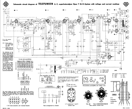
Opus 7 HiFi-System Licensed by Armstrong grille bars
Telefunken Deutschland (TFK), (Gesellschaft für drahtlose Telegraphie Telefunken mbH
- Country
- Germany
- Manufacturer / Brand
- Telefunken Deutschland (TFK), (Gesellschaft für drahtlose Telegraphie Telefunken mbH
- Year
- 1956/1957
- Category
- Broadcast Receiver - or past WW2 Tuner
- Radiomuseum.org ID
- 188910


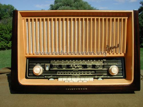
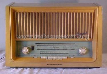
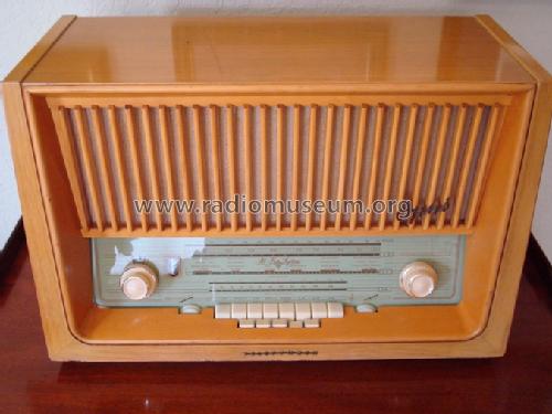
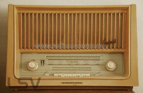
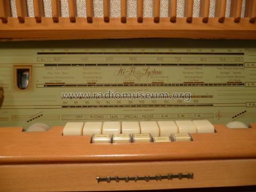
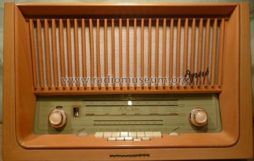
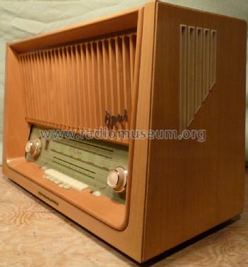
Telefinken Opus 7 / front view

Prospekt

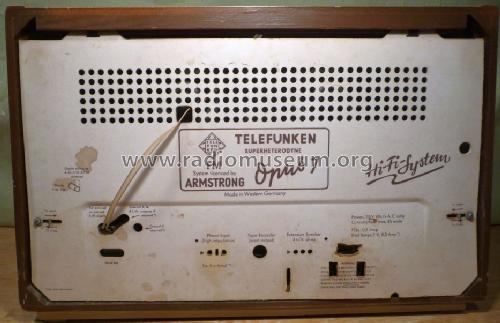
Exportmodell Rückwand,
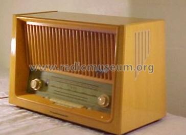
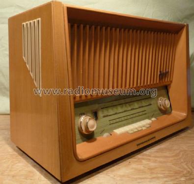
Opus 7, Exportmodell hell


Click on the schematic thumbnail to request the schematic as a free document.
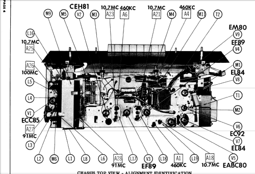
- Number of Tubes
- 9
- Number of Transistors
- Semiconductors
- B250C125
- Main principle
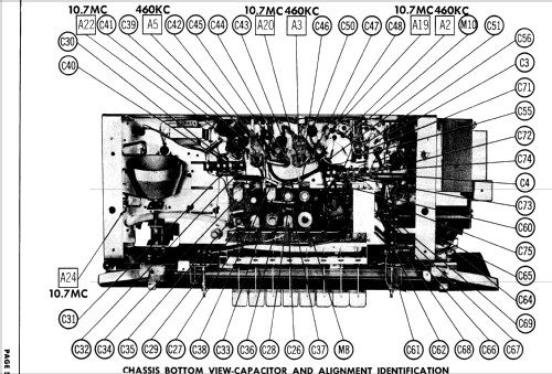
- Superheterodyne (common); ZF/IF 460/10700 kHz; Export model
- Tuned circuits
- 8 AM circuit(s) 12 FM circuit(s)
- Wave bands
- Broadcast, Long Wave, Short Wave plus FM or UHF.
- Power type and voltage
- Alternating Current supply (AC) / 110-120 Volt
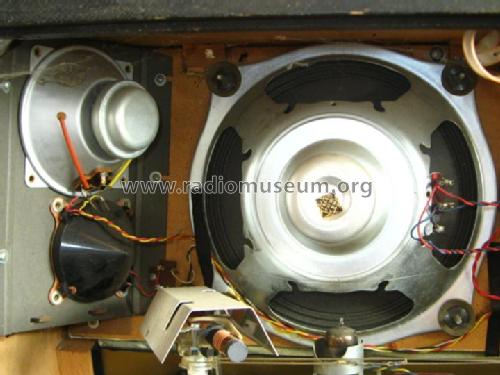
- Loudspeaker
- 6 Loudspeakers
- Power out
- 10 W (unknown quality)
- Material
- Wooden case
- from Radiomuseum.org
- Model: Opus 7 HiFi-System Licensed by Armstrong [grille bars] - Telefunken Deutschland TFK,
- Shape
- Tablemodel with Push Buttons.
- Dimensions (WHD)
- 660 x 415 x 280 mm / 26 x 16.3 x 11 inch
- Notes
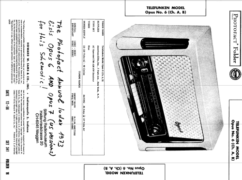
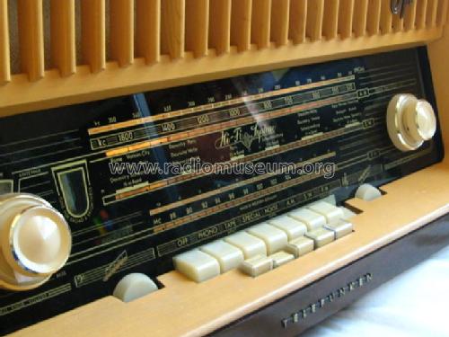
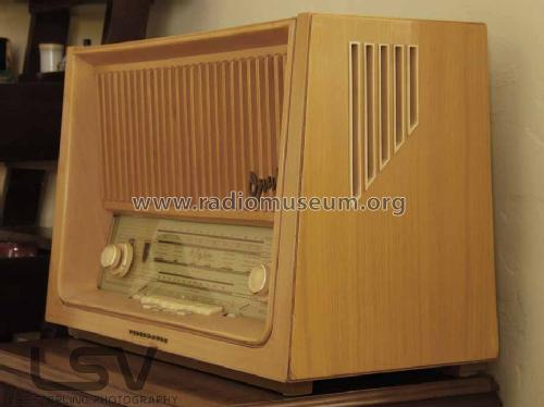
- Export model Telefunken Opus 7 is shown in the Photofact Index as being the same as export model Telefunken Opus 6 which is documented clarly in that said set 341 folder 16 from 12-56 Folder. But Opus 7 has at least the 5 additional push buttons for "Solo, Jazz, Orchester, Bass and Intim" in front of the normal 8 push buttons (both models show). There are at least Version A and B or Chassis. The Opus 7 has been made in two quite different cabinets. One has the usual textile speaker grille in front, the other has vertical wooden bars in front and ony cut outs at the sides in the woods for the other speakers. You find two different pages for them - but not different wones for the color variants which show also different glass scales and knobs.
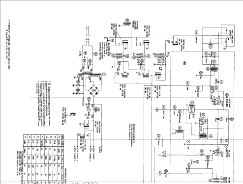
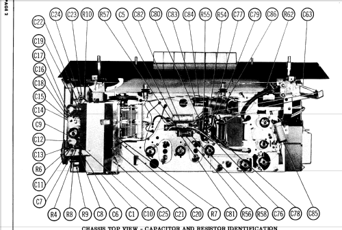
Until we can deliver schematics for the Opus 7 USA we leave the Opus 6 USA schematics according with SAMS also on model Opus 7 USA. Power Supply 60 Cycles. Supplier was American Elite, Inc., 7 Park Ave., New York.
- Net weight (2.2 lb = 1 kg)
- 15.8 kg / 34 lb 12.8 oz (34.802 lb)
- Literature/Schematics (1)
- -- Original-techn. papers.
- Literature/Schematics (4)
- Photofact Folder, Howard W. SAMS (Date Dec. 1956, volume 341, folder 16)
- Author
- Model page created by Ernst Erb. See "Data change" for further contributors.
- Other Models
-
Here you find 3544 models, 3124 with images and 2094 with schematics for wireless sets etc. In French: TSF for Télégraphie sans fil.
All listed radios etc. from Telefunken Deutschland (TFK), (Gesellschaft für drahtlose Telegraphie Telefunken mbH
Collections
The model Opus is part of the collections of the following members.
Forum contributions about this model: Telefunken: Opus 7 HiFi-System Licensed by Armstrong
Threads: 1 | Posts: 2
Dear Members,
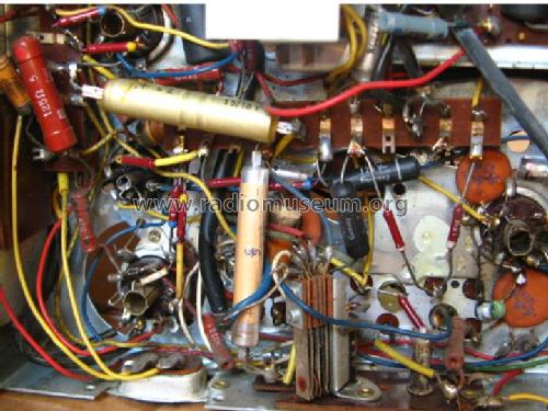
I have been working on the restoration of a Telefunken Opus 7.
Per schematics, screen voltage of EF89 in the last IF stage (tube4) should be 25V but I read 40V. All the components around EF89 are OK (C48,C47,W20,W21,C38 and grid resistor).
Anode voltage is around 220V which should be OK as well.
I swapped the EF89 with the one in previous IF stage (which shows the correct voltage values so I assume it is a good tube), still I read 40V. I have tried 3 different EF89s from other radios I have, the result is same.
Any thoughts about this issue?
Thanks in advance,
Cuneyt
Cuneyt Bakan, 25.Jun.15