1j24b (1j24b)
1j24b (1j24b)
Also known as 1ZH24b, 1sh24b and properly 1Ж24Б
Useful information on these kinds of sub-miniature Rod Pentode tubes (valves):
The 1j24b is still (2011) readily available to purchase as New Old Stock (NOS). Some stock at least is as late as 1991
Nützliche Informationen über diese Art von Sub-Miniatur-Rod Pentode Röhren:
Die 1j24b ist immer noch (2011) leicht zugänglich zu kaufen (2011) leicht zugänglich wie Neu Alte Aktien Kauf (NOS)
To thank the Author because you find the post helpful or well done.
Construction

1j24b 1Ж24Б
Cross-section showing top single filament feed
Glass (grey) aproximately 8mm
To thank the Author because you find the post helpful or well done.
Replacing a DF96
The wiring to a B7G plug for a socket intended for DF96 (DF96 is nominal 24mA @ 1.4V about twice the 1j24b current)

4mm to 6mm of sleeve recommended g1, g2, g3
Wires cut about 8mm
Some IF amp may need neutralisation or additional screening on around the the whole assembly.
If it's a series heater chain a parallel resistor between +f and the -f,g3,s connections is needed. It might be advantageous to put 18 Ohms in series between 1j24b f- and the -f,g3,s plug connection.
Works to some extent with no other modification in an Invicta 29 in place of DF96, but if there is no signal or very weak station then turning up the volume results in some feedback, so additional screening and possibly neutralisation, series resistor etc may be needed.
[Edit: Actually with a very slight IF transformer adjustment the 1j24b replacement is "stable" without screening and the radio working as well if not better than before ]
To thank the Author because you find the post helpful or well done.
Replacing a DAF96
Bonded Germanium diodes have, I think, been available since 1946. This "plug replacement" to save your DAF96 (or possibly DAF91) uses an 1N60 diode or similar.

Some small adjustment of the IF transformer may be needed.
Tested in an Invicta 29.
If there is a series filament chain a suitable parallel resistor across pin 1 and 7 is required as the DAF91 is 50mA (RCA 1S5) and the DAF96 is 25mA (both nominal 1.4V). The 1j24b is 11mA to 13mA depending on voltage (0.9V to 1.4V recommended). If desired 18 Ohm could be in series between the 1j24b filament - (wire 2) and pin 1 of the B7G. This will also slightly reduce HT bias.
To thank the Author because you find the post helpful or well done.
Replacing a DF96
Note that the adapter plug for replacing a DF96 with a 1j24b may need a 100K resistor with 10nF in series from g1 to ground pin of the DF96 socket/plug (or some other adjustment) as the 1j24b may have more gain at higher frequencies and be unstable when the IF is fully tuned.
The capacitor is needed for DC isolation as the DC bias on g1 of the DF96 may be derived from the AM detector diode (Germanium or part of a DAF96 or DAF91).
[Edit: Thinking about this more, the instability if the 1j24b in place of DF96 at IF amp is likely AGC loop oscillating. The the 1j24b is a very sharp cut-off on the g1. The DF96 g1 bias is derived from the AM detector diode.]
To thank the Author because you find the post helpful or well done.
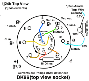
Replacing a DK96 or DK91 with a 1j24b
The DK96 or DK91 are Heptodes used as "frequency changers", i.e. Mixer/Oscillators taking in LW, MW or SW RF from tuned aerial loop or tuned ferrite rod and on the output at Anode the IF frequency (usually between 450kHz and 470KHz).

DK96 Underneath pin view
On the face of it you think you need 1j24b as an oscillator and a separate mixer. But there is a way to do this with a single 1j24b plugged into an unmodified DK96 or DK91 socket. Likely DK92 or DK962 also.
On most Heptode Frequency Changers such as DK96 the anode volts are about the same as HT volts or G2 volts. There is no resistive anode load, just the IF transformer. Yet the anode current is very low (maybe only 200uA), but the g2 current might be 1.4mA. The g4 current might be 120uA. The Oscillator is output / drive on g2 and input/feedback on g1.
I've established already that the rod pentodes work well as oscillators from Screen grid to control grid, but only if anode voltage is very low or anode disconnected. Given the "current mirror" characteristic between g2 and Anode below the pentode knee, that makes sense.

(click for full size)
So logically if I put a large resistor in series with 1j24b anode and decouple it for IF the G2 current and gain should increase and the oscillator work.
What about the Mixer?
I built an AM micro power generator (only a transmitter if you add an aerial). It used anode feedback, a "polycon" and MW ferrite rod for tuning/feedback. I established that using G3 as a mixer input the mixer gain to Anode doesn't depend much on anode volts, hence you get more modulation % AM at 12V HT than 40V etc.
I wasn't sure about the G2 volts as the Invicta 29 I was testing with (uses a DK96) so I tried 22K, 47k Ohms and 4m7H coil and also nothing from G4 pin to g2. None of the variations made much difference.
I calculated that 180k Ohms ought to reduce the Anode volts enough and that 10nF was plenty of decoupling across it.
It worked. Less Mixer gain than the DK96. But very stable and sounds the same otherwise
Reversed from normal tube views
Philips datasheet currents shown. In practice measured with a 1M Ohm input DMM the Anode volts is 6.7V. Which thus means about 400uA. Looking at the curves and assuming g1 on socket is about 0V (200mV below f-) the G2 would likely also be about 400uA. But it's running fine and very stable over all of MW & LW.
Likely a specially designed circuit would perform better and 180K Ohms may not be optimal. But it does work in an unmodified radio as "plug in".
So now I have an Invicta 29 with the DK96 (Ever Ready), DF96, DAF96 and DL96 (all Mullard) now for storage and LT current when battery 1.47V of 67mA. The original nominal 125mA is specified at 1.4V. The HT current is now 5.3mA rather than 6.7mA on Battery of 78V. However Mains operation is now a problem as the lower current draw causes LT to rise to 1.8V! So without some adaptation of the mains adaptor replacing tubes (valves) with lower current draw types may only be "safe" on Battery only sets.
The 18 Ohms is optional since the 1j24b is nomally 1.2V and Dk96 nominally 1.4V. If using in a series chain a parallel resistor may be needed from pin 1 to pin7.
Ironically the replacement of the DF96 with the 1j29b was the most problematic.
DK96 -> 1j24b with parallel RC in series with anode.
DF96 -> 1j24b with series RC in parallel with g1 and ground (may not be needed on some radio sets)
DAF96 -> 1j37b if the volume control on Anode side of pentode, 1j24b + 1N60 otherwise
DL96 -> 1j29b (but only 1/2 filament needed)
Finally
The versatile "rod pentode" can be operated as a diode, (use g1 as anode, ground all other electrodes), Triode (connect g2 to Anode, and ground g3), Pentode, almost a Tetrode (bring g3 a couple of volts positive) and now even "plug in" to a socket intended for a Heptode/Pentagrid frequency changer.
To thank the Author because you find the post helpful or well done.
Note on Plug in 1j24b to DK96 socket
I put a 470K "pot" and 39K series resistor bypassed with 10nF in series between 1j24b anode and the DK96 socket anode pin.
Unsurprisingly at 39K and 505K there was no audio at all. (39K the Anode voltage is too high and the oscillator stops as g2 drops to small value, at 500K the anode voltage too low to get much current at all passing g2 and g3)
Surprisingly the "loudest" setting was measured at 188K Ohms. Very close to my original and first tested value of 180K Ohms. I tried also 22pF instead of 10nF as the bypass on the resistor. With 10nF the tuning of the first IFT is very broad. But the other 3 coils are sharp enough. With 22pf it is not as sharp as the other 3 coils but much narrower. But of course a significant drop in gain.
To thank the Author because you find the post helpful or well done.