3DP1 (3DP1) Polarkoordinaten-Röhre
3DP1 (3DP1) Polarkoordinaten-Röhre

Das angegebene Sockelschaltbild (aus dem Röhren-Codex) ist leider falsch.
MfG DR
Für diesen Post bedanken, weil hilfreich und/oder fachlich fundiert.
3DP1 Sockel
Im ARRL Handbook 1950 habe ich folgende Belegung der Sockelstifte gefunden, von der Unterseite gesehen, vom (einzigen) Führungsstift/~zapfen aus links beginnend im Uhrzeigersinn:
Fig. 49
1 - H, 2 - K, 3 - G, 4 - IS, 5- A1, 6 fehlt, 7 - D3, 8 - D4, 9 - A2, 10 - D2, 11 - D1, 12 - NC, 13 fehlt, 14 - H.
Kein Hinweis auf den Zentralanschluß am Bildschirm.
Unter den Röhrendaten steht:
Electrostatic Cathode-Ray; Heater - 6,3V, 0,6A; Use Oscillograph; Size - 3"; A2 - 2000/1500V; A1 - 575/430V; Cut-Off Grid Voltage -60/-40V; Max Input Voltage (between A2 and any deflecting plate) - 550V; Deflection Sensitivity (DC Volts/inch) - D1,D2 - 200/150V - D3,D4 - 148/111V; Pattern color - Green.
MfG Götz Linß
Für diesen Post bedanken, weil hilfreich und/oder fachlich fundiert.
Eine von dreien wird zerlegt
Bislang bleibt es nach Datenlage ein Geheimnis, weshalb eine Polarkoordinatenröhre 4 Ablenkplatten besitzen soll (wie eine "normale" [kartesische] Oszillographenröhre).
Ergebnisse demnächst hier.
MfG DR
Für diesen Post bedanken, weil hilfreich und/oder fachlich fundiert.

bitte noch nicht zerlegen.
Aus der International Radio Tube Encyclopedia 1959:
CRT für Oszilloskop
14pin-Diheptalsockel (ähnlich wie Oktal, aber größer und mit 14 Stiften): von unten im Uhrzeigersinn: f, k, g, shield, a1, nc., y1, y2, a2, x2, x1, nc., nc., f
Fokus und Ablenkung elektrostatisch
Heizung: indirekt, 6,3V, 600mA
Bildschirm: 76mm Durchmesser, grün, mittel nachleuchtend
Ua1: 575 V
Ua2: 2000V
Ug1: -60V
x-Platten: 0,125 mm/V
y-Platten: 0,167 mm/V
Gruß, H.-T. Schmidt
Für diesen Post bedanken, weil hilfreich und/oder fachlich fundiert.
Geheimnis weitestgehend gelüftet
Danach läßt sich vereinfachend folgendes feststellen:
Die 3DP1 ist von der Elektronenkanone und den Ablenkplatten zunächst einmal aufgebaut wie eine "normale" Oszillographenröhre. An die x-Ablenkplatten wird eine Cosinusförmige und an die y-Ablenkplatten eine Sinusförmige Spannung (passender Amplitude) angelegt. Darauf hin wird auf dem Schirm ein Kreis geschrieben. In Polarkoordinaten ist das die Richting des Winkels φ.
Nun muß noch der Radius r dieses Kreises beeinflußt werden. Dazu dient der Anschluß mitten auf dem Schirm. Innerhalb der Röhre ist das eine Nadel (D5) von ca. 12 cm Länge. Diese Nadel endet ca. 1,5 cm vor den (äußeren) x-Ablenkplatten. Zusammen mit dem Graphitbelag des Kolbens bildet die Nadel einen kegelförmig zylindrischen Kondensator. In Abhängigkeit von der Polarität der Spannung zwischen Belag und Nadel wird r vergrößert oder verkleinert. Die Abhängigkeit zwischen der Größe der Spannung und r ist nicht linear und hängt außerdem davon ab, ob der Strahl in Richtung der x-Ablenkplatten oder der y-Ablenkplatten ausgelenkt wird.
2.9. Special Types of Cathode-ray Tubes.
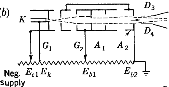
Central-electrode-radial-deflection Type (3DPI).-The purpose of this type of tube is to provide an increased length of time base without increase in the tube size for A-scope applications. This condition is met by making the time base a large circle concentric with the tube axis instead of the customary straight line across the diameter of the tube. When so used, the tube is called a "J-scope." The electron gun used in this tube is standard, being identical to that used in the 3BP1 type. The circular time base is produced by applying voltages in quadrature to the two sets of deflection plates. The signal is applied to an electrode in the form of a tapered rod sealed into the center of the tube face; the electrode extends axially toward, but not as far as, the region of the deflection plates. Contact to this electrode is made by a button that extends through the tube face. A difference of potential between this central electrode and the conducting coating on the bulb produces a radial electric field. Hence, signals applied to the central electrode appear on the trace as inward or outward deviations from the circular trace.
A tube of this type is not adapted to the measurement of the strength of the signal applied to the central electrode because the radial deflection sensitivity is a function of the sign of the voltage applied to the central electrode, the radius of the base circle, and the instantaneous position of the spot on this circle. The electric-field strength at any point in the radial field between the central electrode and the second-anode coating varies as the reciprocal of the distance of the point from the axis of the tube. Hence, the deflection sensitivity decreases in the same manner. Accordingly, the deflection factor, which is the reciprocal of the deflection sensitivity, increases linearly with distance from the central electrode. This behavior is illustrated in Fig. 2-20, which also illustrates that the deflection factor is greater when the radial deflection occurs along the line corresponding to the deflection produced by plates D3 and D4 than when it is along the line corresponding to the orthogonal set of plates D1 and D2.


Because of the complications illustrated in Figs. 2-20 and 2-21, the use of the 3DP1 cathode-ray tube is restricted to the measurement of time relationships.
Die 3DP1 ist also nur dazu zu gebrauchen, um die Zeitpunkte einer Ablenkung in r Richtung zu bestimmen, nicht aber um die Größe der Spannung in r Richtung korrekt anzuzeigen.
MfG DR
Für diesen Post bedanken, weil hilfreich und/oder fachlich fundiert.
Bilder von der 3DP1

Die prinzipielle Form der Elektronen-Kanone der 3DP1 ist im nächsten Bild dargestellt.
Um an die Informationen zu kommen, mußte eine 3DP1 "geschlachtet" werden (sorry).

Hier liegt sie friedlich neben einer guten 3DP1.

Bei der geöffneten 3DP1 wurde der Graphitbelag teilweise entfernt, damit das System in seiner korrrekten Lage zu sehen ist. Auch mußten die Haltefedern in Richtung Schirm gedreht werden, weil der Röhrenhals zu kurz abgeschnitten werden mußte.
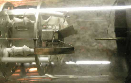
Deutlich ist hier die Spitze der "Nadel" zu erkennen. Die keramischen Abstandshalter des Systems sind mittels einer Keramikmasse fixiert. Das könnte darauf hindeuten, daß die 3DP1 vor allem für mobilen Betrieb vorgesehen war.
Zusammen mit den im Post 5 angegebenen Daten kann man den Eindruck gewinnen, daß die Polarkoordinaten-Röhre 3DP1 im Grunde nur durch die eingeschmolzene "Nadel" aus einer gewöhnlichen Oszillographen-Röhre 3BP1 entstanden ist.
MfG DR
Für diesen Post bedanken, weil hilfreich und/oder fachlich fundiert.
Testbetrieb der 3DP1
Mittels eines Generators, der zwei mit einander in der Phase um 90 Grad gegeneinader verschobener sinusförmigen Spannungen liefert (Sinus & Cosinus), kann bei X/Y Ansteuerung ein Kreis geschrieben werden.
Wird ein hierzu synchronisierter (periodischer) Einzelimpuls auf die Nadel gegeben, erhält man das folgende Bild.
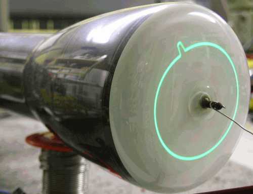
Gibt man eine synchronisierte Rechteckschwingung auf die Nadel, entstht das folgende Bild.

Aus dieser Darstellung sieht man deutlich, daß die 3DP1 in Abhängigkeit vom Winkel unterschiedlich empfindlich ist.
MfG DR
Für diesen Post bedanken, weil hilfreich und/oder fachlich fundiert.
Mathematische Verfahren

Hallo Herr Rudolph,
es ist schon interessant zu sehen, was man früher für 'Klimmzüge' machen mußte, wenn man etwas umgerechnet darstellen wollte.
Viele Utensilien und Geräte sind ( zum Glück ) völlig aus dem technischen Leben verschwunden.
- Ganze Säle voller Zeichnenbretter
- Rechenschieber in der Brusttasche des weissen Arbeitskittels als Zeichen für den Ingenieur
- Doppelt logarithmisches Papier zur Auswertung von Messergebnissen. ( Das Integral der Kurve wurde berechnet, indem man die Kurve mit der Schere ausgeschnitten hat und mit einer Feinwaage gewogen hat. )
- Analogrechner zur Optimierung von dynamischen Systemen. ( Fahrzeug - Federung )
Alles Dinge, die Heute bequem und genau von einem PC mit der geeigneten Software
viel genauer dargestellt werden können.
Allerdings gibt es jetzt neue Probleme. Meine Azubis rechnen : 25/5, natürlich mit dem Taschenrechner, finden als Ergebnis 20 und akzeptieren das kritiklos !
Schöne Grüße
Georg Beckmann
v
Für diesen Post bedanken, weil hilfreich und/oder fachlich fundiert.
Radial Deflection (J Scope)
In "Rider, J.F.; Ulsan, S.D.: Encyclopedia on Cathode-Ray Oscilloscopes and their Uses, Rider, 1950", einem Werk, das in quasi epischer Breite auf 982 Seiten den technischen Stand (von 1950) der Oszilloskope und ihrer Teile dokumentiert, findet sich auch eine Beschreibung der 3DP1 Röhre.
Radial Deflection (J Scope)
A modification of the basic dual electrostatic deflection system shown so far in this chapter is the tube wherein a third electrostatic deflection element is used. This type of tube is an outcome of the need for presentation along polar co-ordinates, although such presentation is possible without recourse to this third electrode. The Armed Forces made use of this type of tube in a number of radar units and the display was identified as the J scan (tube type 3DPI). Fundamentally, the tube is a standard electrostatic type cathode-ray tube, except that an additional electrode in the form of a thin metallic rod is mounted at the center of the screen. The rod extends through the space between the screen and the deflection area, although not into the area occupied by the deflection plates. The other end of the rod protrudes through the screen where a snap-on clip enables electrical contact with the rod. The tube is shown in Fig. 6-15.

Fig. 6-15. Type 3DP1 J tube, showing the central deflection electrode protruding through the screen.
The radial deflection electrode is clearly visible at the center of the screen. Some tubes, such as the 3CP1, also provide an etched scale on the screen for the determination of distances to the target, picked up by the equipment. Fig. 6-16 affords a general idea of the construction and the relative location of the radial deflection electrode and the conventional deflection plates.

Fig. 6-16. Internal construction of the J scope.
In the operation of this tube, the trace on the screen is organized along polar co ordinates. Two sinusoidal voltages of equal magnitude and 90' out of phase are applied to the two pairs of deflection plates. The resultant trace on the screen is a circle as in Fig. 6-14C.

This is the time base for the display. The speed with which the spot travels around the screen describing the circle, or the angular velocity of the rotating voltage vector, is a function of the frequency of the voltages applied to the deflection plates. Thus the time base can be calibrated in terms of time in microseconds. Now, if a voltage is applied to the radial deflection electrode, it will set up a radial field between it and the second-anode coating on the inside of the tube envelope. Therefore, the beam which follows a circular path in the space between the deflection area and the screen is moving through the electrostatic field between the radial deflection electrode and the second anode coating. How this second electrostatic field will affect the beam depends upon the instantaneous magnitude and polarity of the second field. By suitable arrangement, the signal voltage applied to the radial electrode can be such as to momentarily deflect the beam away from its path, that is, kick the beam outward, causing an instantaneous increase in the length of the radial voltage vector which is describing the circle. The extent: of this "kick" is a function of the amplitude and time duration of the radial deflection voltage.

Fig. 6-17. (A) shows the circular time base produced on the screen of the J scope before a deflection voltage has been applied. In (B), the circular base has been modified by a momentary voltage pulse applied to the radial deflection electrode, in (C) a pulse of the opposite polarity is applied to the electrode, and (D) shows the appearance of the trace after a sine-wave voltage is impressed on the radial deflection electrode.
Thus in Fig. 6-17A, we show the circular time base without any voltage applied to the radial deflection electrode. The circular trace is the result of the two sinusoidal voltages applied to the two pairs of deflection plates. Now a momentary signal voltage in the form of a pulse is applied to the radial deflection rod, and this pulse voltage has such polarity as to kick the beam outward. The appearance of the trace now is as in Fig. 6-17B. A change in the polarity of the radial deflection pulse can cause the trace to kick inward as in Fig. 6-17C. If the voltage applied to the radial deflection electrode is a sine wave, the final trace on the screen will appear like that shown in Fig. 6-17D.
It is significant to note that the frequency of the signal which produces the time base (circle) is not changed when the radial deflection voltage is applied; in other words, the voltage applied to the radial deflection rod does not influence the operation of the regular deflection system. The circular moving beam is changed in its orbit by the radial deflection field after it has left the regular deflection system.
The latter point is important because of circuit modifications which enable the development of a similar trace without recourse to a second radial deflection field. This is explained fully later; for the present, let it suffice to say that the voltages applied to the regular deflection plates, which develop the circular time base, are so modified momentarily by a supplementary signal voltage, as to produce traces like those shown in Figs. 6-17B through D. Without this supplementary voltage the trace appears like Fig. 6-17A.
Der Text bestätigt die Anwendung der 3DP1 als Display für Radar-Anwendungen.
MfG DR
Für diesen Post bedanken, weil hilfreich und/oder fachlich fundiert.