Ballast tubes in filament regulation of VFO tubes
Ballast tubes in filament regulation of VFO tubes

Ballast tubes versus solid state regulators in VFO tube filament regulation
By Kurt Schmid, DH3PJ (unpublished manuscript)
VFO stability of vacuum tube-based receivers among other things depends on the presence of well controlled supply voltages. In the majority of better quality vintage radios B+ is held constant using simple voltage regulator tubes (gas discharge types). In a few high-end communications receivers e.g. from Collins, National and Hallicrafters the filament current of the VFO tube also is regulated. In this case current regulators (preferentially iron-hydrogen types) are connected in series with the VFO tube filament. In contrast to B+ voltage regulators these 'ballast tubes' are known being rather poor performers.
The Collins-designed military receiver R-390A/URR is the best known example of a radio equipped with a ballast tube. Constant current regulation is obtained using series connection of the filaments of the PTO tube (5749, 6,3V/.3A), the BFO tube (5749, 6.3V/.3A), and the ballast tube 3TF7 (.3A). A separate winding of power transformer T801 delivers 25.2 volts AC to the above chain.
Evaluation of the voltage-current characteristic of the 3TF7 ballast tube
Amperite documentations show only generic voltage-current relationships arguing that the characteristics of the many types are all about identical3. Nevertheless, here the current regulation properties of the 3TF7 ballast tube (Amperite) were evaluated recording the voltage-current characteristic. The following simple test arrangement was used.
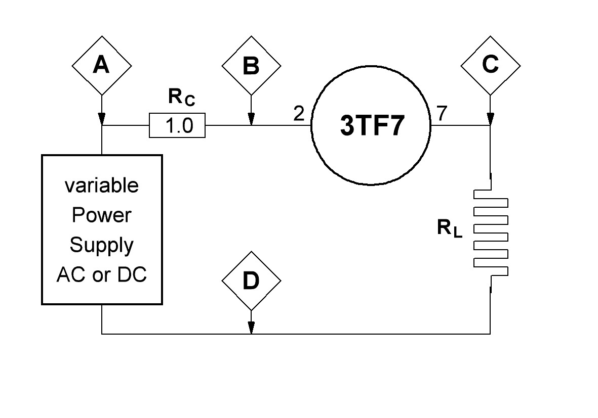
Figure 1: Test setup to measure the voltage-current relationship of a current-regulator
A variable power supply (AC or DC) is connected to a loop consisting of the 3TF7 current regulator and a load resistor (power resistor RL = 42 Ω). The latter emulates the PTO and BFO tube filament load. In contrast to the filament of a vacuum tube a fixed resistor has the advantage to show a constant load over time. The variable power supply was manually adjusted such that across the 3TF7 stepwise increasing DC-voltages between 3.0 and 23.0 volts were measured. Voltage measurement was performed using a DVM (HP/Agilent 34401A) connected to measurement points B and C. Due to the considerable thermal time lag of the current regulator the power supply voltage was continuously readjusted until the voltage across the 3TF7 regulator became constant at the desired level. In accordance with the Amperite specs and with the later presented results with increasing voltage the lag was as much as several minutes for final readings.
The current within the loop was derived from measurement of the voltage drop across resistor RC (point A and B) by calculation: I = U/R (R = 1.0 Ω)

Figure 2: Plot of the voltage-current characteristic of a ballast tube (3TF7)
For the interpretation of the above chart knowledge of the numbering system that Amperite used for its 'automatic current regulators' is helpful. In general the Amperite number approximately denotes the current-voltage threshold value. For example 3TF7 denotes a threshold current of .3A and a threshold voltage of 7.0 volts.
The herein presented charts were prepared using SigmaPlot v.12 (Systat). As expected, at low voltages a steep rise of current is observed. Evidently within the range of 3-6 volts no regulation exists. Thereafter, the slope gradually decreases. This is interpreted as current regulation becoming more and more effective. At the threshold voltage (7.0 V) the curve flattens further. The most accurate but an evidentially not ideal regulation is obtained in a plateau range between 13 and 20 volts. Measured threshold voltage and threshold current correspond well with the values as defined and published by Amperite1,2.
Effects of changing supply voltages on the time course of regulated output voltage
The observed thermal time lag seriously impairs regulation quality when the supply voltage shows abrupt changes because the ballast tube needs considerable time for regulation. To quantify this effect the following measurement protocol was used. During the nominal supply voltage of 25.2 VDC (Fig. 1, B-D) output voltage to the load (Fig. 1, C-D) was continuously monitored by a chart recorder (Gould TA 240) and taken as control period. Thereafter, the supply voltage (= input voltage) was abruptly reduced from 25.2 to 22.0 volts. After a steady current state was reached the supply voltage was switched back to normal (25.2 V) and the recovery characteristic of the current was monitored until the control situation was re-established. Changes in loop current could be calculated from the voltage drop across RC (1 Ω)

Figure 3: Time course of the regulated output voltage from the 3TF7 ballast tube in response to input voltage steps
In trace B recording of the ongoing input voltage (supply voltage) is shown. The resulting regulated output voltage to the load (42 Ω) is shown in trace A. At the nominal supply voltage of 25.2 VDC regulated output voltage across the load was 12.9 volts at a current of 307 mA. Switching the input voltage to 22.0 volts was followed by a steep reduction (- 825 mV) of regulated output voltage. There was a slow but incomplete recovery from the reduced output voltage. Steady state was reached after about 3 minutes. Regulated output voltage remained 430 mV below the control voltage. Switching input voltage back to 25.2 volts was followed by a steep increase of regulated output voltage clearly surpassing the control value of 12.9 volts. The regulated output voltage slowly recovered completely and reached control level after about 3 minutes.
The above results uncover at least two inherent properties of ballast tubes responsible for poor regulation behavior:
a) the slow regulation characteristic leads to a very poor initial regulation
b) the voltage drop of the unregulated input even after a long time isn't fully compensated.
In the experiment depicted in figure 3 steady state regulation was calculated as:
delta regulated voltage / delta input voltage = 0.43 V / 3.2 V = 0.134 (~ 1/7.5)
Development of ballast tubes solid state replacements
Numerous attempts have been made to overcome the shortcomings of ballast tubes. Especially the 3TF7 was subject of many reports. To name a few drawbacks:
a) the most prominent disadvantage is the rather poor regulation property
b) the iron wire is prone to break,
c) last but not least the 3TF7 as well as some other ballast tubes (e.g. 4H4C) become more and more scarce and expensive5.
I won't go into detail but at least two categories of replacements can be discriminated. Substitutes using simple resistors or tubes with suitable filament parameters are pure workarounds showing no regulation properties at all. Solid state replacements are either of constant current or constant voltage type. They outperform the original 3TF7 to various extend.
Dallas Lankford4 and followers published solid state replacements using three-terminal fixed-voltage regulators (e.g. 7812) delivering 300 mA at 12 VDC to the series connected filaments (6.3 volts, each) of the PTO and the BFO tubes in the R-390A. Regulation is very satisfactory. Unfortunately these devices are quite bulky and exhibit a high power dissipation (around 8 watts) requiring voluminous heat-sinks.
With the recent availability of miniature switching regulators a 3TF7 replacement could be designed matching the form factor of the 3TF7, i.e. a direct plug-in replacement could be built. BTW, TF denotes T 6½ bulb, 9 pin miniature.
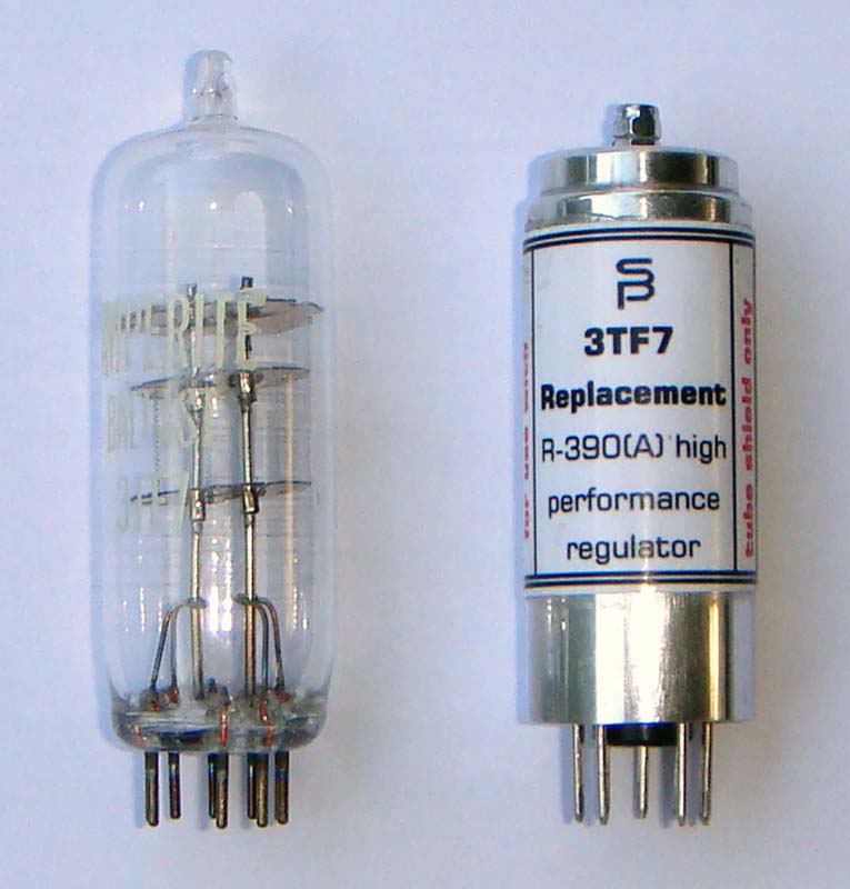
Figure 4: Photo showing an original 3TF7 ballast tube (Amperite) side by side with a switching solid state 3TF7 replacement
Switching DC-DC down converters can reduce heat generation drastically. The illustrated module (right side) runs very cool and dissipates around 1 watt, only. It's tested to work in the R-390 and R-390A receivers. Switching frequency has proved to have no negative effect on HF properties of the receiver.
It's already visually evident that the 3TF7 module is more robust than the fragile original. Amperite specifies life expectancy of their ballast tubes with 2,000 hours. That's a fraction of the usual life-time of solid state devices. The question arises if the stabilization properties of solid state modules justify a replacement of the original ballast tube.
Comparison of regulation characteristic of the 3TF7 ballast tube with the 3TF7 solid state replacement
Two measurement series were conducted (cf. figure 5), either using the original ballast tube (filled circles) or the solid state replacement (open circles). The power supply (cf. figure 1) was set to different input voltages (B-C) and the regulated output voltages (C-D) were measured. Unregulated input voltage was plotted against regulated output voltage.

Figure 5: Chart demonstrating the relationship between unregulated input voltage and regulated output voltage for the genuine 3TF7 and the 3TF7 replacement
At low input voltages both devices showed no regulation (linear input to output voltage relationship). The ballast tube (filled circles) started regulation at about 20 VDC input voltage. When increasing input voltage to 30 VDC regulated output voltage still rose from 12.5 to 13.1 volts. The 3TF7 replacement (open circles) started regulation at 15 VDC input voltage producing an output voltage of 12 VDC. This remained absolutely constant when input voltage was increased up to 30 volts. This result strikingly demonstrates the superior stabilization quality of the solid state regulator over the ballast tube.
A last experiment was conducted to verify that the above test results correspond to effects observed in a real environment situation.
Effects of power line voltage variation on frequency output of the R-390A PTO either equipped with the original ballast tube or the replacement
Two measurement series were performed in an EAC R-390A. The radio was either equipped with the original ballast tube or the solid state replacement.
The power line input of the R-390A receiver was connected to a VARIAC that could be switched from 230 VAC (normal European line voltage) to 210 VAC. With a chart recorder (Gould TA 240) the line voltage, the regulated B+ (+150 VDC), and the output frequency of the PTO were registered. The latter one was measured with a frequency counter connected to a digital-to-analogue converter (1 Hz resolution). PTO frequency was set to about midrange.
Measurements confirmed that the regulated B+ is stabilized perfectly. B+ remained constant at +149,6 VDC independent of line voltage variations from 230 VAC to 210 VAC and back to 230 VAC. Therefore this trace is not included in the following chart.

Figure 6: Effects of power line voltage changes on the output frequency of the PTO of the R-390A receiver either equipped with the original 3TF7 or with the 3TF7 replacement module
Traces A & B (figure 6) show results with the original 3TF7 current regulator. Traces C & D show results with the 3TF7 replacement inserted into socket RT510 in the IF chassis. Traces B & D show the power line voltage (lower part partly suppressed). The VARIAC was switched to low voltage (210 VAC) for 1.25 min.
When the original 3TF7 was in place decrease of the line voltage was followed by a delayed increase in PTO frequency (A). Maximum increase was about 12 Hz followed by a slow decrease reaching a steady state at 8 Hz. When the 3TF7 was replaced by the replacement module (C) and the line voltage was decreased no frequency change was observable. The time course of the frequency changes very well reflect the results as illustrated in figure 3.
Power line voltage variations induced changes in output frequency of the 70H-12 PTO do not result from B+ changes but from heater current changes. Measurements confirm the early results of Dallas Lankford. The presented results demonstrate that adequate stabilization of filament supply of the VFO tube definitely improves over-all receiver frequency stability.
Preliminary results show that solid state replacements of other current regulator types, e.g. Amperite 4H4C used in other high-end communications receivers (National and Hallicrafters) let expect similar performance improvements6
References
1. Amperite, Automatic Current Regulator (9 pages, undated)
2. Amperite, Ballast-Regulating Tube, Bulletin AB-51 (1965)
3. Jacobi, A.P., Ballast Tube Handbook, Antique Electronic Supply (AES)
4. Lankford, Dallas, 3TF7 Replacement, The Hollow State Newsletter 24:5-6 (1991)
5. Osterwald, Ray, The National NC-400 Communications Receiver, Electric Radio 262:36 (2011)
6. Schmid, Kurt, 4H4C Ballast Tube Replacements, Electric Radio 264: 40 (2011)
To thank the Author because you find the post helpful or well done.