Beam Power Tetrode

ID: 146010
Beam Power Tetrode  
29.Jul.07 14:04
0

Konrad Birkner † 12.08.2014 (D)
Articles: 2333
Count of Thanks: 19
Konrad Birkner † 12.08.2014

From time to time the question is made why the base diagram of a Beam Power Tetrode is similar to that of a Pentode, displaying 5 electron handling elements.

Even the manufacturers literature is sometimes suspected to err, and even attempts are made to have our tube pages in RMorg "corrected".

There are some good explanations of that design, but they are hidden in long treatise.
Here a recapitulation:
The Beam Power Tetrode has 5 elements, but the beam confining electrodes are not a grid. In particular RCA insisted in the name tetrode to distinguish it from the pentode patented by Philips. The beam power tetrode  acts almost like a pentode and both use the same symbol.

There is no discrepancy in calling it a tetrode.


To thank the Author because you find the post helpful or well done.

 2
 
30.Jul.07 06:11

Mario Bermejo (RA)
Articles: 237
Count of Thanks: 22
Mario Bermejo

It is interesting to add that RC-15 tube manual shows a base diagram that includes the the beam deflection elements and describes the 6V6GT as a Beam Power Amplifier , but later editions, such as the RC-17, refer to the same tube with the same name but omit the base diagram that includes the deflection elements, using the common pentode base with supresor grid and ommiting the designation tetrode or pentode alltogether. (both in their Spanish versions, published by ARBO editores, Buenos Aires)

Sylvania tube manual also skips the tetrode/pentode issue by calling the 6V6 "Power amplifier"

What really added wood to the fire is the fact the defelection elements are connected to the cathode inside the tube, same way it occurs with the supressor grid although they are two different things.

Mario

To thank the Author because you find the post helpful or well done.

 3
Beam Power Tubes 
19.Feb.09 15:40

Dietmar Rudolph † 6.1.22 (D)
Articles: 2492
Count of Thanks: 47
Dietmar Rudolph † 6.1.22


Beam Power Tubes sometimes are called Tetrodes but sometimes also Pentodes. Indeed, they are a mixture of both types. If the electrodes are counted, they look like a tetrode, if the characteristic is regarded, they behave more like a pentode.
 
 
The first figure [7] shows the arrangement of electrodes in vacuum tubes. (A) shows a cylindrical arrangement which is typical for small tubes, and (B) shows an elliptical arrangemet which is typical for power tubes. In (C) the various grids of a pentode are shown, and in (D) the construction of a beam power amplifier tube is shown. Here the suppressor grid is repaced by a beam confining electrode or beam forming plate.
 
The figure 10.22 [2] shows the cutaway view of a 6L6 „Beam Power Tetrode“.
 
 
The constructional features are shown in the next figure [4]. The cross-section of the tube shows the beam forming within this tube.
 
 
We now look to the characteristics of pentode and tetrode, fig. 3.48 [5] and fig. 5.20 [4]
 
 
Pentodes have a soft transition in their characteristic for low anode voltages, and tetrodes suffer from a region with a falling characteristic due to secundary emission from the anode at low anode voltages. The beam power tube remedies both effects, the soft transition, and the falling characteristic.


4.12 The Beam power Tetrode [1]


The beam power tube is essentially a tetrode of improved design to eliminate the effects of secondary emission by taking advantage of the electron space charge existing between the screen and the plate. In conventional tubes the electrons start at a small cylindrical cathode and spread out more or less radially as they flow to the anode. This makes the electron density near the plate small, and the space charge is too weak to be of any particular help in repelling secondary electrons back to the plate. By arranging the electrodes in the fashion shown by Fig. 4.26 [i.e. figures 10.22 [2] and 5.21 [4]], it is possible to obtain a nearly parallel flow and maintain a high density beam throughout the path. Hence the term "beam" tube. The electrons start from, a flattened cathode and are prevented from spreading radially by beam forming plates located on each side of the path and connected to the cathode. An additional improvement is obtained by winding both grids to the same pitch and carefully aligning the screen grid so that it falls in the " shadow " of the negative control grid. This reduces the screen current and improves the tube efficiency.


Figure 4.27 shows the potential distribution in a beam tube with a plate voltage below the screen voltage. Electrons passing the screen are decelerated as they approach the plate and form a dense space charge. This produces a potential depression and provides a barrier to the flow of secondary electrons from plate to screen. Imagine a lone secondary electron in such a position confronted by a crowd of repulsive primary electrons rushing toward it. At low plate voltages the primary electrons are slowed down even more and produce a still lower potential minimum. Thus secondary emission is effectively suppressed without a third grid.


The characteristic curves for a small beam power tube are given by Fig. 4.28. These curves show good design because the plate current rises rapidly until the knee of the curve is reached. This permits a maximum plate voltage swing along the load line without driving the control grid positive. Since this provides the utmost in alternating output for a given d c input, a beam power amplifier is relatively efficient as well as providing more amplification than does a triode. The lower curves show an interesting and typical tetrode secondary emission dip near the left hand end. At low currents the small space charge cannot depress the potential enough to return the secondaries to the anode. Fortunately, a normal load line falls well above this region.

The beam tetrode design is used only for power amplifier tubes where currents are high and efficiency is important. Most voltage amplifiers operate at such small currents that efficiency is secondary, and pentodes do a satisfactory job. In beam tubes the role of the screen as a shielding electrode is often secondary; its main function is to accelerate the electrons to reach the plate even with low platevoltages.
 
A closer look to the characteristic [2]
 
The measured plate current vs. plate voltage characteristics of a beam power tube are shown in Fig. 10.24.


These curves have the same general aspect as the curves of a pentode except that the shoulder of the curves is sharper. Secondary emission distortion of the characteristics is effectively eliminated except for the curves of the lowest plate current corresponding to control grid voltage close to cutoff, where a small inflection of the curves is evident.


Some other features of these curves are also interesting. For relatively high control grid voltages the curves exhibit a slight overlap and also a very steep rise with plate voltage, culminating in a slight cutback before continuing to rise at a slow rate.
 

To understand the last above mentioned effect, let us trace backward one of the large current curves, e.g., the curve for zero control grid voltage. This value of control grid voltage permits a large current to flow from the cathode toward the plate. As the plate voltage is made more negative, the electrons get slowed down more and more in passing from screen grid to plate, and as a result, the space charge density increases and the depression of the potential profile becomes more pronounced, as in going from curve a to b in Fig. 10.25. As the plate potential decreases further, the potential of the minimum decreases at an increasingly faster rate that may, if the current is sufficiently high, lead to an instability, which causes the minimum to jump to zero, as shown in the change from c to the dashed curve of d.


When the condition of d exists, a so called virtual cathode is formed at the point of zero potential. Some of the electrons will get past this point and the rest will be reflected toward the screen grid. Electrons that go on to the plate observe the diode space charge law; and since the current is decreased by reflection though the potential difference between the virtual cathode and the plate stays fixed, the distance between the virtual cathode and the plate must increase. This causes the curve to move to the left to some position such as e. Corresponding points are shown on the cur rent voltage charaeteristic of Fig.10.24. Further decrease in plate voltage increases the reflected current and moves the curve farther to the left. The plate current drops very rapidly in this region because the action is the same as that in a diode in which the plate voltage is being decreased at the same time as the cath ode plate spacing is being decreased.

Upon an increase of the plate voltage, the virtual cathode will move to the right, with a continuous decrease in the reflected current. This can continue to the point d in Fig. 10.25. At a certain point the rate of increase of current with voltage may become infinite, and the current will tend to jump from f to g, as shown in Fig.10.24. Current transmission is now complete and the current will increase slowly with plate voltage beyond this point as shown. Actually, the jumps and the resultant hysteresis loop will occur only under ideal conditions. Because the electrons have a small spread in velocity, the characteristic will exhibit an S shaped reverse kick as shown.

The beam power tube is designed specifically for power production. It is a little simpler to build than the pentode and has a larger area of uniform characteristics. However, if the voltage current excursions take the operating point out of the region of uniform characteristics, the distortion increases much more rapidly than with the pentode.

Practical Beam Tubes. [4]
The beam tube finds use as a power tube from small to moderately high power ratings. It is used for both audio frequency and radio frequency power amplification and has tended to supersede pentode and sereen grid tubes for such applications.
 
 
The symbol of a beam power tube shows the next figure [7].
 
 
[1] Hill, W.R.: Electronics in Engineering, McGraw-Hill, 1949
[2] Spangenberg, K.R.: Fundamentals of Electron Devices, McGraw-Hill, 1957
[3] Spangenberg, K.R.: Vaccum Tubes, McGraw-Hill, 1948
[4] Terman, F.E.: Radio Engineering, McGraw-Hill, 1947
[5] Eastman, A.V.: Fundamentals of Vacuum Tubes, McGraw-Hill, 1949
[6] Ghirardi,A.A.: Radio and Television Troubleshooting and Repair, Rinehart, 1955
[7] Korneff, T.: Introduction to Electronics, Academic Press, 1966


To thank the Author because you find the post helpful or well done.

 4
The beam tetrode Knee 
21.Feb.09 05:06

Joe Sousa (USA)
Editor
Articles: 667
Count of Thanks: 19
Joe Sousa

Dear Dr. Rudolph,

Thank for the excelent overview of Pentode vs Tetrode operation! The material from various sources sheds new light in my understanding of curve behaviour at the knee.

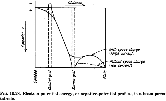
One key point that this clarified for me is that the purpose of the beam is to retain high electron density on the way to the plate, as opposed to concentrate a space charge that had become rarified before the beam plates.

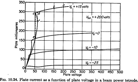
This realization explains to me the slight tetrode-like dip that is seen in most beam tetrode curves at low current. At low current, there is not enough beam current for effective secondary emission repulsion.

In  a recent restoration effort of a Sonora TE-38 phonograph,  I thought to replace a 70L7 beam tetrode with a 117L7. As the link shows, I learned that there is a lot of variation of beam tetrode design between these two beam tetrodes near the knee, where plate voltage is low.

The design of behaviour at the knee became most important for Beam tetrodes meant for application in American low voltage AC/DC radios. The B+ in these radios is only around 110V. It took several beam tetrode design iterations for knee behaviour to be optimized at low plate voltage, as seen in a 50C5.

At the end of the tube era, the KT88 (Kinkless-Tetrode-88) may represent the finest acchievement in the design of the space charge control near the plate, to obtain high power, high efficiency and high linearity, especially in ultra-linear configuration, where 40% of the plate voltage is applied at the tetrode via a transformer tap. Looking at the cuves it is apparent that low plate voltage at low plate current still shows some kink, but this region of operation is never used in normal power audio amplification.

Toward the end of the tube era, small VHF preamp tubes such as the 6AG5 beam tetrode and the 6CY5 tetrode show the other end of the effort at controlling the space charge for minmum transit time, and maximum gm. But keep in mind that transit time depends strongly on control grid to cathode spacing.

The 6AG5 was marketed as a pentode by RCA, but the cuves and direct observation of the element shapes show that it is a small beam tetrode with a small frame grid.

In some of the text scanned by Dr Rudolph, the utility of the beam tetrode for RF was asserted as insignificant, because the RF frequencies at the time were mostly below 30MHz, and at these frequencies, the most useful tube feature was the elimination of Miller feedback capacitance by the screen grid in a pentode or conventional tetrode.

So, it seems that the beam tetrode became the high performace tube of choice for high audio power, as was originally intended, but also for high frequency. The high frequency advantages go beyond the mere shielding effect of the screen grid.

One last bit of recent experience with small beam tetrodes is highlighted in the difference between the step response of a 6CY5 VHF small signal tube and a 6GM6A video amp tube. From the outside, the two tubes appear very similar, but their switching speed is remarkably different, with the 6GM6A Video tube being much slower than the 6CY5 VHF tube.

The following two scope photos show switching action at 50MHz and 100MHz for the 6CY5 VHF beam tetrode. Switching time is critical in mixer operation. The longer the switching time, the shorter the active time, hence the lower the IF output.

Now notice in the following two scope photos how much slower the falling transition is at the plate of the 6GM6A Video beam tetrode. At 100MHz switching frequency, the wave no longer looks square.

I used a Tektronix PG502 pulse generator and the Tektronix 2467B 400MHz oscilloscope for these measurements. The schematic for the setup is as follows:

The original motivation for these measurements was to see if there was an advantage in in the dual conversion scheme used in the Meissner 8C 88-108MHz FM tuner. This tuner uses a single conventional variable local oscillator runing around 50MHz to convert the FM band frequencies around 100MHz, twice, in two successive mixers. The first IF is variable and tuned around 50MHz, and the second IF is fixed at 10.7MHz. The RF and LO frequencies are related by RF=LOx2+10.7MHz. The reason for the double conversion was the higher conversion gain and lower noise figure obtained by mixing with the LO around 50MHz, instead of 100MHz, as is usually done. The two mixing stages used two 6AG5 pentodes/beam-tetrodes.

Once more, special recognition to Dr. Rudolph for serving as the stimulus for me to share these results.

-Joe

To thank the Author because you find the post helpful or well done.