In "G. G. Blake: History of Radio Telegraphy and Telephony, Chapman & Hall, 1928" pp. 252 - 259 some more inventions ofvalves with more than 3 electrodes are presented.
VALVES WITH MORE THAN THREE ELECTRODES
Several types of four electrode valve have been invented (527).
ARCO AND MEISSNER.
Fig. 143A, which is taken from their 1914 patent (474), shows a four electrode valve generating circuit. In the same patent a circuit for obtaining uninterrupted oscillations is shown, in which two three electrode valves are connected in parallel so as to be operative in alternate half periods of the A.C. supply ; but experiments demonstrated, they state, " that the action of the relay (valve) and the energy generated thereby is greater when . . . instead of the simple lattice electrode there are employed two electrodes (E, E1 fixed opposite to one another, which electrodes form the primary path of the relay and to which the alternating current is led." They further state that these electrodes are preferably formed as interengaging combs or spirals.
HULL'S PLIODYNATRON (488), (456), (108).
In America, A. W. Hull invented a four electrode valve, which he called the " Pliodynatron." This was made by the American G.E.C. As its name implies, it is really a combination of the Pliotron " with the " Dynatron."
Fig. 143B and Fig. 143C show the circuits employed respectively by Hull for transmission and reception with this valve. Fig. 143D is a diagram of a Hull Pliodynatron, constructed by the American G.E.C. for transmission purposes.
FLEMING'S FOUR ELECTRODE VALVE (489), (1009).
In 1920* Prof. Fleming described his four electrode valve in a paper before the Wireless Society of London, at the Institution of Civil Engineers. {* It is interesting to recall that it was during this year, on June 15th, 1920, that the Marconi Company conducted a radio telepbony test from their station at Chelmsford, on which occasion Dame Nellie Melba's voice was heard in Persia.}
He described several uses to which it could be put, and gave several circuits and characteristic curves.
Fig. 144A is a diagram of this valve. The filament, F, is surrounded by four convex metal plates, C1, C2, P and P,. Plate C1, in the diagram has been bent out of its proper position, so as to allow the filament to be seen. The valve in use is arranged as shown in the diagramatic plan, Fig. 144B, where C is the connection to the " collecting " plates, C1, and C2.
Fig. 144C shows the connections given by Fleming for use of this valve as a detector, operating a relay.
THE VARIABLE ANODE TAP.
It has been shown that it is often possible to increase the output of a valve generator, by connecting the anode to a point a certain distance down the aerial tuning inductance instead of connecting it to the last turn of the latter. The theory of this is given in Ref. (717).
THE WESTERN ELECTRIC COMPANY's DOUBLE GRID VALVE (1008).
This valve is designed for amplifying, in connection with microphonic control in radio telephony. Its connections are illustrated in Fig. 145.
JOHN SCOTT TAGGART's FOUR ELECTRODE VALVE (1008).
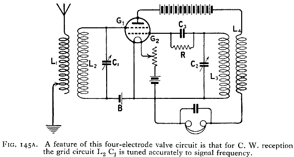
Scott Taggartpatented a four electrode valve, having two grids, in 1919 Fig. 145A is a circuit reproduced from the specification showing one manner in which the valve may be employed in a receiving circuit. Coupled to the aerial coil L1, is a tuned circuit L2, C1, connected across the filament and the grid G1. A suitable negative potential is applied to G1, by a grid battery connected as at B. The second grid circuit is formed by the grid condenser C3, and gridleak R, and the tuned circuit L3C2.
For C.W. reception the circuit L2C1 is tuned to signal frequency; the local oscillations, of such frequency as will give the desired beat note, are produced by suitable coupling between L3 and the coil L4 in the anode circuit, and adjustment of the condenser C2. The grid G1 is thus used for amplification, while G2 is employed in connection with the rectifying process.
ANODE HEATING CONTROL. (497).
In 1921 the "Gesellschaft für drahtlose Telegraphie" patented a four electrode valve for an entirely new purpose in radio telegraphy, i.e. to control the overheating of the valve anode. The scheme is indicated in Fig. 146.
When the anode A becomes overheated, it emits electrons, which pass to a relay electrode C, and a current flows through relay R, and the contacts at E are broken.
THE NEGATRON (501), (777), (993).
The chief use of this valve is for the production of continuous oscillations. It can also be employed for reception of C.W., as an amplifier, as a limiter, or as a radio telephonic modulator.
The Negatron, which is due to John Scott Taggart, has two anodes, as shown in Fig. 147, which gives a negatron circuit for the production of continuous oscillations.
A is the main anode, and A1 the diversion anode. The valve is operated at saturation point, and when this has been arrived at by suitable adjustment of filament temperature and H.T. supply, the valve will oscillate over a wide range of frequencies determined by the constants of the circuit L1C1.
The action of the valve is due to negative resistance effects. If the normal grid potential is zero, the electrons from the filament divide themselves between the two anodes. When the potential of main anode A is increased, the potential of the grid is also raised. Consequently, the main plate will be robbed of a portion of its electron supply, owing to an increased number of electrons going over to the diversion anode A1.
The actual effect of an increase of potential on the main anode, therefore, is to produce a diminution in the current in the main anode circuit, i.e. to produce a negative resistance effect.
FIVE ELECTRODE VALVE OF THE MARCONI COMPANY. (986)*
In 1919 the Marconi Company patented a method of producing oscillations by means of a thermionic valve, having one filament, two grids, and two plates. {* See also Lee De Forest's five electrode valve, patented in 1915 Ref. (1003) ; also (993).}
Q. A. BRACKETT's FIVE ELECTRODE VALVE (1000).
The 1919 patents covering this valve have been assigned to the Metropolitan Vickers Company. Fig. 148 illustrates its functions. A steady electron stream takes place between filament F and plate P, through the telephones T.
The second filament, F1, and the electrodes, P1 and P2, are connected respectively to the middle and ends of inductance L. When oscillations are being received, a continuous rectified current passes between F1 and P1, P2, in the form of an electron stream from the filament. This interferes with the electron stream between F and P, and so controls the current in the telephone circuit.
SIX ELECTRODE VALVE (996).
In 1913 E. F. W. Alexanderson inventeda method of amplifying both half waves of an oscillation by means of a valve having two plates, one filament, two grids, and an additional electrode kept at a positive potential to prevent static reaction between the two grids.
DULL EMITTER VALVES (532), (533), (1014 to 1017) -
The object of these valves is to obtain an increased emission of electrons from the filament, and so effect an economy in the current required to heat it. An alternative method is to reduce the gauge of the filament; but there is a limit to this, and these filaments are very fragile, and have only very short lives. This latter method, therefore, has not found much favour.
VON LIEBEN.
In 1911 Von Lieben, as previously stated, coated the filament of his valve with calcium or barium oxide.* {* Wehnelt had already shown the effect of a lime coated filament in1904 in another connection (1016).}
In America, platinum filaments, or filaments made of platinum alloy, coated with a mixture containing oxides of calcium, strontium, barium, etc., have been employed with considerable success. It is only necessary to heat the filament of these valves to a dull red heat in order to obtain a free emission of electrons.
COOLIDGE (1014).
In 1911 W. D. Coolidge patented the employment of thorium oxide in the preparation of tungsten filaments.
LANGMUIR. (1015).
The following is a description of a dull emitter filament developed in America by Dr. Langmuir in 1914.
This filament is made of tungsten, to which has been added-about 1 per cent. of thorium. After special heat treatment, it is claimed that the electron emission is increased as much as one hundred thousand times that of a piece of tungsten filament at the same temperature (532). By the employment of these thoriated filaments, therefore, a much lower temperature is necessary, and not only is a great saving of current effected, but at the same time the life of the filament is nearly doubled.
During the last two or three years many improvements have taken place in the manufacture of this type of filament, which is used in numerous examples of dull emitter valves now on the market.
THE GENERAL ELECTRIC COMPANY.
The General Electric Company have also carried out much research work on dull emitter valves. See the work of Thompson and Bartlett (1017)
WESTERN ELECTRIC COMPANY (227).
In America, this company produced a valve in which the grid and filament are arranged so as to be in extremely close proximity, and the anode is also placed as near as possible to the grid, so that it will work on extremely low plate voltages.
In these valves the filament is wound over the grid, so that the latter is not in the space between the plate and the filament.
The grid is in the form of a wire loop, coated with an insulating layer of nickelous oxide, and the filament is wound round it. The plate is a sheet of metal at each side of and very close to the grid and filament.
The Western Electric Company also make a valve of this type for transmitting. In this case, a glass tube runs through the centre of the valve for purposes of water cooling. The grid takes the form of a cylinder of metal, over which the filament is wound, and this is again surrounded with a cylindrical plate.
THE " THERMION " VACUUMLESS VALVE.
E. V. Myers in America(1101 and 1102) has recently invented a valve, illustrated in Fig. 149, which operates in air at ordinary atmospheric pressure. It has no glass bulb, but merely a removable perforated cover which is only intended to protect it from dust and draught. The special filament is .035in. in diameter and operates on 110 volt lighting mains at about ½ ampere. In use the filament temperature is about 800 degrees centigrade.
THE PHOTOTRON.
This American valve is a type of photoelectric cell. Instead of relying for its electron supply from the usual heated filament it obtains an electronic emission from the surface of a plate coated with a photo active alkali metal, such as potassium, under the action of light.
In appearance it is like an ordinary radio valve and is mounted upon an ordinary standard valve base.
Langmuir's patent from 1913 is not mentioned in this text. The Pliodynatron in Fig. 143D, however, is similar to the tube cited by Nesper.
The literature cited by Blake is here in a PDF file.
Kind regards, Dietmar
To thank the Author because you find the post helpful or well done.