rca: RF Transformer analysis
rca: RF Transformer analysis

Fellow radiophiles,
A while back I came across an RF transformer following the 12BA6 RF preamp of a 6 tube AC-DC Silvertone Radio, that had a fixed tuned primary. I did not understand the design purpose for this fixed tuned primary.
![]()
Recently, while restoring this RCA 6 tube AC-DC set, I noticed the same fixed-tuned primary at the RF transformer following the 12BA6 RF preamp. I had the set on the bench, so I decided to measure the RF transformer and simulate it's operation to learn how it worked.
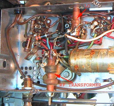
The RF transformer is not shielded and is located at the lower half of the photo.
I measured the primary inductance of this transformer with the transformer in place, using my Rohde&Schwarz BN6100 inductance meter.
The inductance meter can be used to measure inductance and self-resonant capacitance, including external capacitance soldered to it's terminals.
I got 3mH with a Q=10 at 41kHz and a self-resonant capacitance of 70pF at 340kHz. The capacitance includes internal parasitics and the external 47pF.
Next, I measured the low frequency non-resonant transformer coupling ratio, and found 15:1 at 10kHz from primary to the top of the tapped secondary. I had the tuning dial at the top of the range.
The following model evolved as more measurements of voltage transfer were accumulated. Accounting for Q properly was very important to get reasonable model aggreement. RQp and RQs model the Q of the windings, beyond what is already implicit in the DC series resistances R3 R4 and R5.
Note the large 23pF self capacitance of the primary represented by C2.
I chose to break up the primary into two inductors for modeling purposes in LTspiceIV. Three inductors L1a, L2a and L2b form an ideally coupled transformer as defined by K12. The loosely coupled primary had 3mH of uncoupled inductance, and only around 200uH was coupled 100% to the secondary. This gave just under 10:1 coupling ratio, which I deemed close enough to the 15:1 measurement.
The components outside the dashed line box enclosing the transformer, correspond to components in the schematic, but I was a bit careless, and did not retain the same reference designators.
The 12BA6 RF preamp tube was modeled as a transconductor with 2mS. Somehow, my measurents could not summon up the full rated 4mS of transconductance, but the character of the gain is still correct.
![]()
The first multi point frequency sweep extablished the voltage transfer characteristic from the grid of the RF preamp to it's plate. The load is the low Q fixed tuned primary resonating at 340kHz, and the input test voltage was 130mVrms. A reasonable agreement was obtained between the table of measured values above and the simulated curve in the following plot by lowering the 12BA6 gm to only 2mS.
Each of the curves in this plot was done with the RF tuning capacitor at different positions, as listed in the ".step" simulation command. The straight curve without dips corresponds to tuning at 1.6MHz and also corresponds to the measured table.
![]()
The following plot shows the overall voltage transfer from RFgrid to Mixer grid. The marked values are in reasonable agreement with the table of measured values above. While the RF preamp does not add a lot of gain to the radio, in particular at the upper end of the band, it is very effective at improving image rejection with the steep decay above resonance.
The curves show a sharp notch that is common to all curves around 2MHz, which is just beyond the plot. This notch is caused by a resonance between the 2.2pF coupling capacitor and the 3mH primary.
Each curve represents a different tuning capacitance. Image rejection is most important when tuning below 1.2MHz, where a strong local station above this frequency will have a heterodyne image.
For example, my local 1.4MHz station has a heterodyne image 455KHz below 1.4Mhz, at 945kHz. The 1.4MHz station could be heard when the radio is tuned to 945kHz, unless the RF Loop and transformer reject this frequency. The green curve for tuning at 1MHz shows over 30dB of rejection for the image of a 1.4MHz signal. This rejection is added to the main loop antenna, which should be at least 40dB with loop Q=100. The overall image rejection should be around 80dB
![]()
It appears that the primary purpose of this RF transformer is to improve image rejection, while adding a modest amount of gain, up to 15dB at 560kHz, but the gain at 1.6MHz is about 0dB.
This tilt in gain complements the expected lower Q of the loop antenna at lower frequencies. The reduced loop reactance at lower frequencies lowers the Q, as the loop wire resistance becomes more significant compared to the inductive reactance.
The overall sensitivity of the set is clearly higher than that of 5 tube AC-DC set, and the resulting improvement in AGC from higher overall gain is very noticeable.
Regards,
-Joe
To thank the Author because you find the post helpful or well done.
Wider frequency sweep
The following plot shows a wider frequency sweep from 40kHz to 4MHz, with only two sets of curves for two tuned frequencies at 620kHz and 1.39MHz.
The transformer ratio becomes apparent at the low frequencies well away from resonance.
The 2MHz notch caused by the 2.2pF capacitor and the 3mH inductance of the primary is clearly seen. Note how this notch is independent of tuning frequency.
This notch is what causes the steep drop in response above resonance, that adds several tens of dB to image rejection.
![]()
Regards,
-Joe
To thank the Author because you find the post helpful or well done.
Radiotron RF amps
> I came across an RF transformer following the 12BA6 RF preamp of a 6 tube AC-DC Silvertone Radio, that had a fixed tuned primary. I did not understand the design purpose....
Radiotron has some words, Chapter 23, page 922 (pg 11 in this PDF):
Radiotron Designers Handbook (Headfonz)
Radiotron Designers Handbook (AX84)
Radiotron Designers Handbook Ch 23 (Headfonz)
Radiotron Designers Handbook Ch 23 (AX84)
To thank the Author because you find the post helpful or well done.