Tuning fork oscillators
ID: 136991
Tuning fork oscillators
24.Mar.07 19:03
14550

Tuning fork oscillators
Stable low frequency sources were often required in several applications, precision clockworks, facsimile equipment, instrumentation, navigation and avionics systems. When each single bistable multivibrator (flip/flop) required a double triode, the use of quartz crystals in the generation of low frequencies was very expensive: a suitable 100KHz crystal was bulky and brittle and it still required a lot of bistable multivibrators to scale down to frequencies under 1KHz. It is true, there were some attractive solutions to divide by five or by ten with a single twin triode, but also in this way many components could be required. One of the best solution found to the problem of generating stable low frequency oscillations was the use of tuning fork resonators.
The operating principle of the tuning fork was simple and well known. Electronic industry quickly developed highly advanced solutions to achieve simple, reliable and extremely stable oscillators.
A typical tuning fork oscillator, used in facsimile equipment, is shown in fig. 1.
Two windings, a drive coil and a pick-up one, were placed close to the tines of the tuning fork, which was in the feedback loop of a three stage amplifier. This circuit gave stable oscillations at the resonating frequency of the fork.
Since the amplifier was designed to operate at a near constant drive level, the precision and the stability of the oscillator depended upon the precision and the stability of the tuning fork itself. Every effort was done to improve this component. The fork was made of nickel-steel alloys, with extremely low temperature coefficient of expansion. Tines were accurately balanced and thermally compensated, either with carbon steel laminations or with bimetal reeds. Fork units were then vacuum sealed, to avoid any environmental influence over their frequency and their Q.
In the fifties, absolutely remarkable overall performances were reached. Temperature stability better than plus or minus 0.2 part per millions per degree centigrade was given over ambient temperature from 10 to 65 degrees centigrade. Overall stability within plus or minus 3 ppm without oven, 1 ppm after warm-up, was attainable. Stability as high as 1 part in 15 millions was possible if the fork was aged and operated into a thermostatic oven. (*)
The next three pictures show overall view and internal details of a tuning fork unit built by Philamon Laboratories Inc., Westbury, Long Island, N.Y.
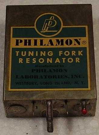
Fig 2: The complete tuning fork resonator. On the bottom right of the unit well visible is the exhaust hose.
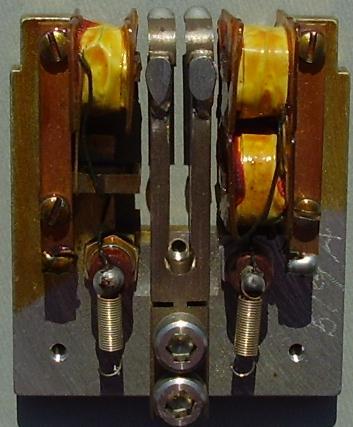
Fig. 3: View of the same unit open. Starting from left, the pick-up coil, the fork and the two driving coils. On the top of both tines there are the tuning and balancing masses, part of them supported by the two right angle reeds. The coils were connected to the pins on the case by the two springs visible aside the fork, near the bottom.
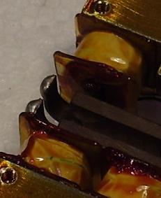
Fig.4 Details of the bimetal temperature compensating reeds.
This unit was designed to operate at 1350 hertz. It was originally mounted on rubber spacers. Dimensions are 55 x 68 x 25 mm; weight is 240 grams.
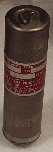
The last picture shows another tuning fork resonator built by American Time Prods. Inc., New York, under license of Western Electric Co. This unit was designed to operate at 240 Hz, therefore it was higher than the resonator shown in the previous figures, 93 mm in height by 25 mm in diameter. It has a 9 pin miniature base. On the top is visible the air exhaust hose.
(*) Stability figures taken from Radio Engineering Handbook, Fift Edition, by Keith Henney.
Stable low frequency sources were often required in several applications, precision clockworks, facsimile equipment, instrumentation, navigation and avionics systems. When each single bistable multivibrator (flip/flop) required a double triode, the use of quartz crystals in the generation of low frequencies was very expensive: a suitable 100KHz crystal was bulky and brittle and it still required a lot of bistable multivibrators to scale down to frequencies under 1KHz. It is true, there were some attractive solutions to divide by five or by ten with a single twin triode, but also in this way many components could be required. One of the best solution found to the problem of generating stable low frequency oscillations was the use of tuning fork resonators.
The operating principle of the tuning fork was simple and well known. Electronic industry quickly developed highly advanced solutions to achieve simple, reliable and extremely stable oscillators.
A typical tuning fork oscillator, used in facsimile equipment, is shown in fig. 1.
Two windings, a drive coil and a pick-up one, were placed close to the tines of the tuning fork, which was in the feedback loop of a three stage amplifier. This circuit gave stable oscillations at the resonating frequency of the fork.
Since the amplifier was designed to operate at a near constant drive level, the precision and the stability of the oscillator depended upon the precision and the stability of the tuning fork itself. Every effort was done to improve this component. The fork was made of nickel-steel alloys, with extremely low temperature coefficient of expansion. Tines were accurately balanced and thermally compensated, either with carbon steel laminations or with bimetal reeds. Fork units were then vacuum sealed, to avoid any environmental influence over their frequency and their Q.
In the fifties, absolutely remarkable overall performances were reached. Temperature stability better than plus or minus 0.2 part per millions per degree centigrade was given over ambient temperature from 10 to 65 degrees centigrade. Overall stability within plus or minus 3 ppm without oven, 1 ppm after warm-up, was attainable. Stability as high as 1 part in 15 millions was possible if the fork was aged and operated into a thermostatic oven. (*)
The next three pictures show overall view and internal details of a tuning fork unit built by Philamon Laboratories Inc., Westbury, Long Island, N.Y.
This unit was designed to operate at 1350 hertz. It was originally mounted on rubber spacers. Dimensions are 55 x 68 x 25 mm; weight is 240 grams.
The last picture shows another tuning fork resonator built by American Time Prods. Inc., New York, under license of Western Electric Co. This unit was designed to operate at 240 Hz, therefore it was higher than the resonator shown in the previous figures, 93 mm in height by 25 mm in diameter. It has a 9 pin miniature base. On the top is visible the air exhaust hose.
(*) Stability figures taken from Radio Engineering Handbook, Fift Edition, by Keith Henney.
To thank the Author because you find the post helpful or well done.