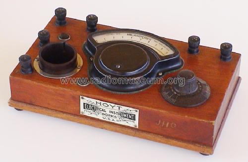
Tube Tester 100
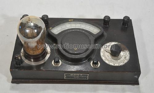
Hoyt Electrical Instrument Works; New Hampshire
- Country
- United States of America (USA)
- Manufacturer / Brand
- Hoyt Electrical Instrument Works; New Hampshire
- Year
- 1922 ?
- Category
- Service- or Lab Equipment
- Radiomuseum.org ID
- 77554
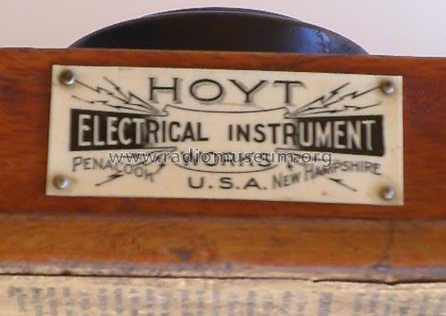
Label in front
ebay.com VK:jeanstin2 #281185534356
ebay.com VK:jeanstin2 #281185534356
VK:jeanstin2 #281185534356
ebay.com VK:jeanstin2 #281185534356
- Power type and voltage
- Storage and/or dry batteries
- Material
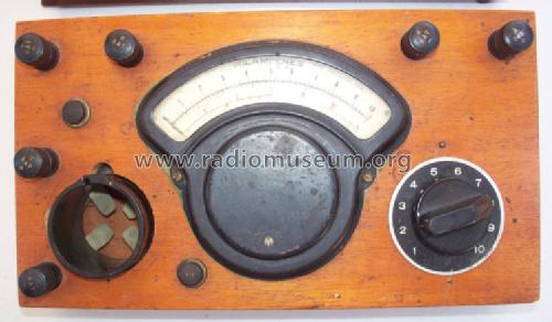
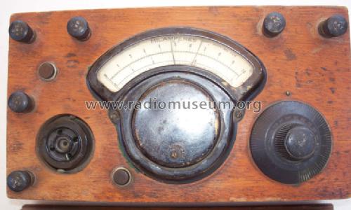
- Wooden case
- from Radiomuseum.org
- Model: Tube Tester 100 - Hoyt Electrical Instrument
- Shape
- Tablemodel, with any shape - general.
- Dimensions (WHD)
- 225 x 70 x 125 mm / 8.9 x 2.8 x 4.9 inch
- Notes
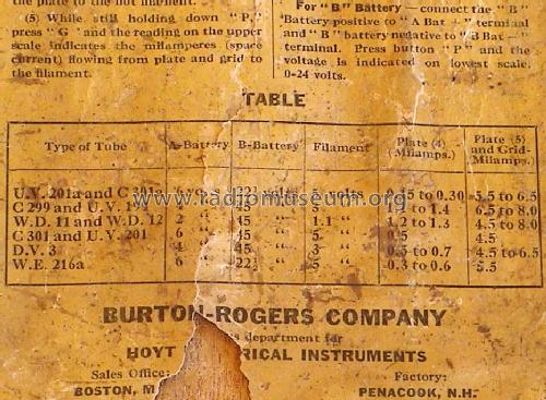
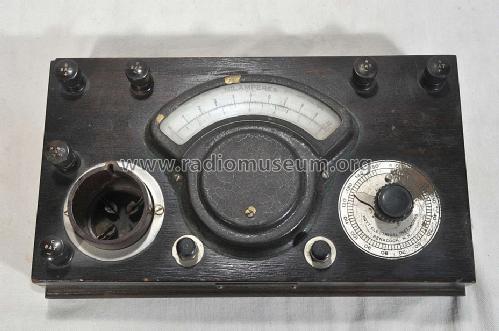
- A, B and C battery binding posts allowing to test Types UV201, UV-201A (UV201A, 201A), C-301A (C301A, 01A), C-299 (C299), UV-199 (UV199, 99), WD-11 (WD11), WD-12 (WD12), C-301(C301, 301), DV-3 (DV3), WE, 216A and UV-200 (UV200) tubes. This device and the model 200 were often sold through the Burton-Rogers Company, which had a sales office in Boston, Mass.
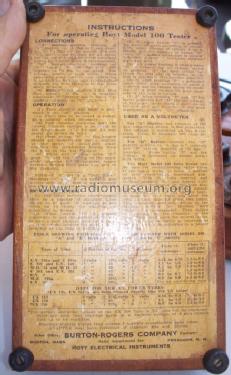
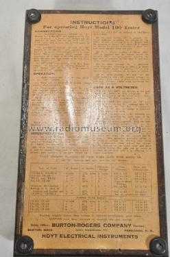
Instructions for operating Hoyt Model 100 Tester:
A-6 volt "A"-Battery can be used for all tubes, but the use of 4 volts for 3-volt tubes and 2 volts for 1.1-volt tubes is recommended.
For B-batterys use vltages shown in the tables. When measuring plate current only (operation 4) as high as 90 volts may be used after the tube has been found free from short circuuits.
For making Grid Bias test use C battery posts.
Operation
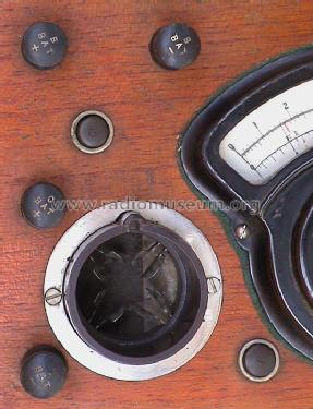
1) Turn rheostat dial back to zero which is the "off" position.
2) Place tube to be tested in socket, using adapter when necessary.
3) Turn rheostat clockwise until the correct filament voltage is indicated on the 6-volt scale (3 and 5 volt points are shown in red).
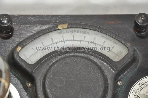
4) Pressbutton "P" - the pointer should act immediately and the reading on the upper, or milampere scale, registers the milamperes flowing from the plate to the hot filament (Remark EE: we know that the electrons go the other way).
5) While still holding down "P", press "G" and the reading in the upper scale indicates the milamperes (space current) flowing from plate and grid to the filament.
Interpretation
1) The table indicates characteristic tests on a number of standard tubes known to be good. If readings do not come up to these, the chances are something is wrong.
2) When button "P" is pressed (operation 4) and the pointer drops back to zero, a poor vakuum, poor emission or or an open circuit between the plate and its terminal at the base is indicated.
3) If when button "P" is pressed, the meter indicates according to column 5 (in table) instead of column 4 as it should, and the pressing of button "G" (with "P") causes no change in pointer deflection, a shor circuit exists between plate and grid.
4) If a proper reading is shown when "P" is pressed but no change occurs on pressing "G", an open circuit between the grid and its terminal at the base is indicated.
5) If after pressing "P", a deflection much lower than according to table 4 is shown and no change occurs on pressing "G" a poor vakuum or poor emission in the tube is certain.
Used as a voltmeter
For "A" Battery - set rheostat at 150 and connect as shown in first paragraph. The voltage is indicated on the 6-volt scale (also 10 milamps. 600 ohms resistance).
For "B" Battery - connect the "B" Battery positive to "A Bat +" terminal and "B" Battery negative to "B Bat -" terminal. Press Button "P" and the voltage is indicated on lowest scale 0-24 volts.
The table is shown on a photo here which is taken from the bottom of these instructions.
- Net weight (2.2 lb = 1 kg)
- 1 kg / 2 lb 3.2 oz (2.203 lb)
- Mentioned in
- Antique Radio Classified (Vol.14 No 7, July 1997, Page 14)
- Author
- Model page created by Ernst Erb. See "Data change" for further contributors.
- Other Models
-
Here you find 7 models, 6 with images and 0 with schematics for wireless sets etc. In French: TSF for Télégraphie sans fil.
All listed radios etc. from Hoyt Electrical Instrument Works; New Hampshire
Collections
The model Tube Tester is part of the collections of the following members.