- Country
- Japan
- Manufacturer / Brand
- Panasonic, Matsushita, National ナショナル (also tubes); Osaka
- Year
- 1976–1978
- Category
- Broadcast Receiver - or past WW2 Tuner
- Radiomuseum.org ID
- 78570


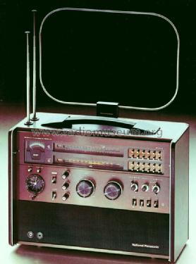
Komplett mit aufgesteckter Rahmenantenne

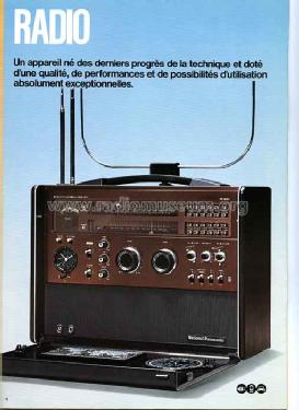


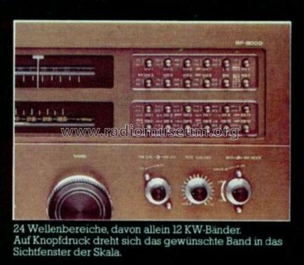
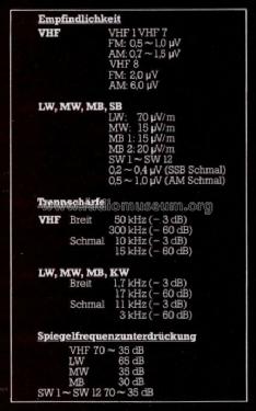
Original prospekt.
Original prospekt.

Original prospekt.

Original prospekt.

Original prospekt.
Original prospekt.

Original prospekt.

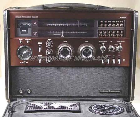
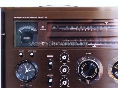
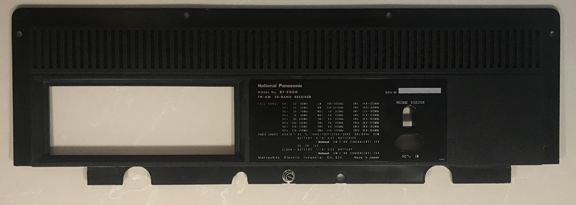
Frontplatte
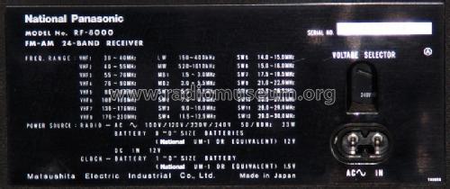
Typenschild


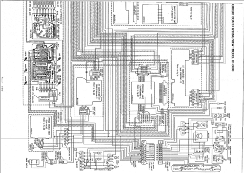
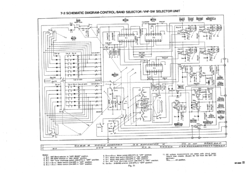
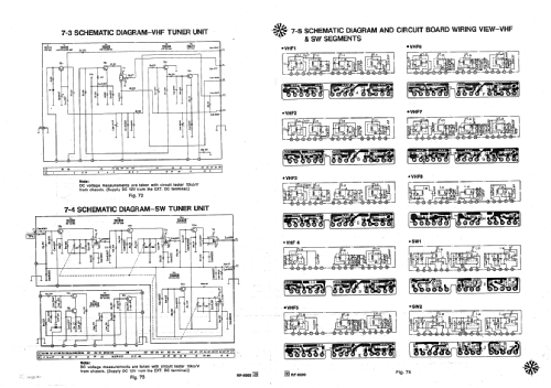
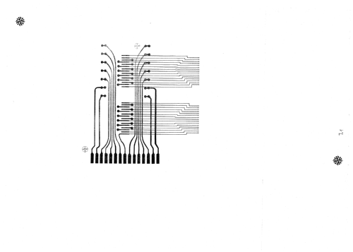
Click on the schematic thumbnail to request the schematic as a free document.
- Main principle
- Superhet, double/triple conversion; ZF/IF 1700/455 kHz
- Wave bands
- Broadcast, Long Wave, more than 2 x SW plus FM or UHF.
- Power type and voltage
- Line / Batteries (any type) / 120 / 8 x 1,5 Volt
- Loudspeaker
- 2 Loudspeakers
- Power out
- 5 W (unknown quality)
- Material
- Various materials
- from Radiomuseum.org
- Model: RF-8000 - Panasonic, Matsushita,
- Shape
- Portable set > 8 inch (also usable without mains)
- Dimensions (WHD)
- 20.2 x 14.25 x 8.4 inch / 513 x 362 x 213 mm
- Notes
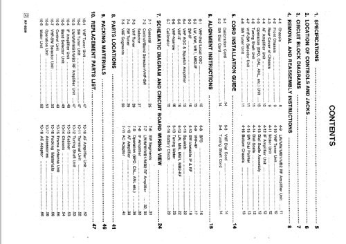
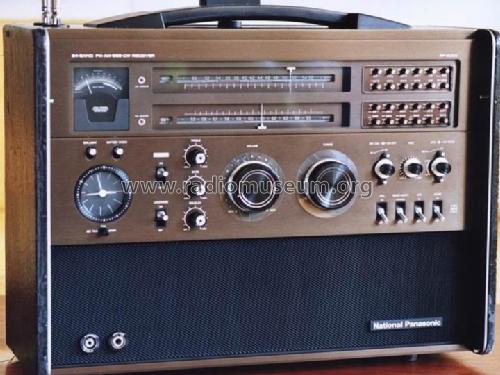
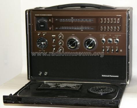
- Panasonic 24-Band FM-AM-SSB-CW Receiver RF-8000;
Shortwave coverage 14 bands from 1,6 - 30 MHz, double conversion above 5,5 MHz, VHF coverage 8 bands from 30 - 230 MHz; AM, SSB (BFO), FM on VHF; motor driven tuning, crystal marker on SW; clock / timer. Output power: 2.8W (DC), 5.0W (AC). One more battery is required for clock. Speakers: 18 x 10 cm.
- Net weight (2.2 lb = 1 kg)
- 21 kg / 46 lb 4.1 oz (46.256 lb)
- Price in first year of sale
- 3,400.00 $
- Source of data
- Handbuch VDRG 1977/1978
- Mentioned in
- World Radio TV Handbook 1976
- Literature/Schematics (1)
- Antique Radio Magazine - Italy, Club Antique Radio Magazine (n. 105, jan-feb 2012)
- Author
- Model page created by Martin Bösch. See "Data change" for further contributors.
- Other Models
-
Here you find 3119 models, 2902 with images and 643 with schematics for wireless sets etc. In French: TSF for Télégraphie sans fil.
All listed radios etc. from Panasonic, Matsushita, National ナショナル (also tubes); Osaka
Collections
The model is part of the collections of the following members.
Forum contributions about this model: Panasonic,: RF-8000
Threads: 1 | Posts: 4
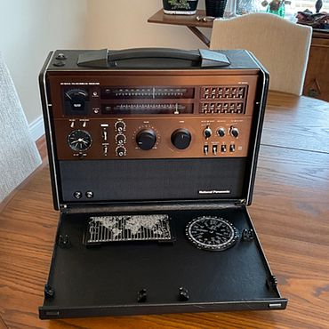
NATIONAL PANASONIC RF-8000
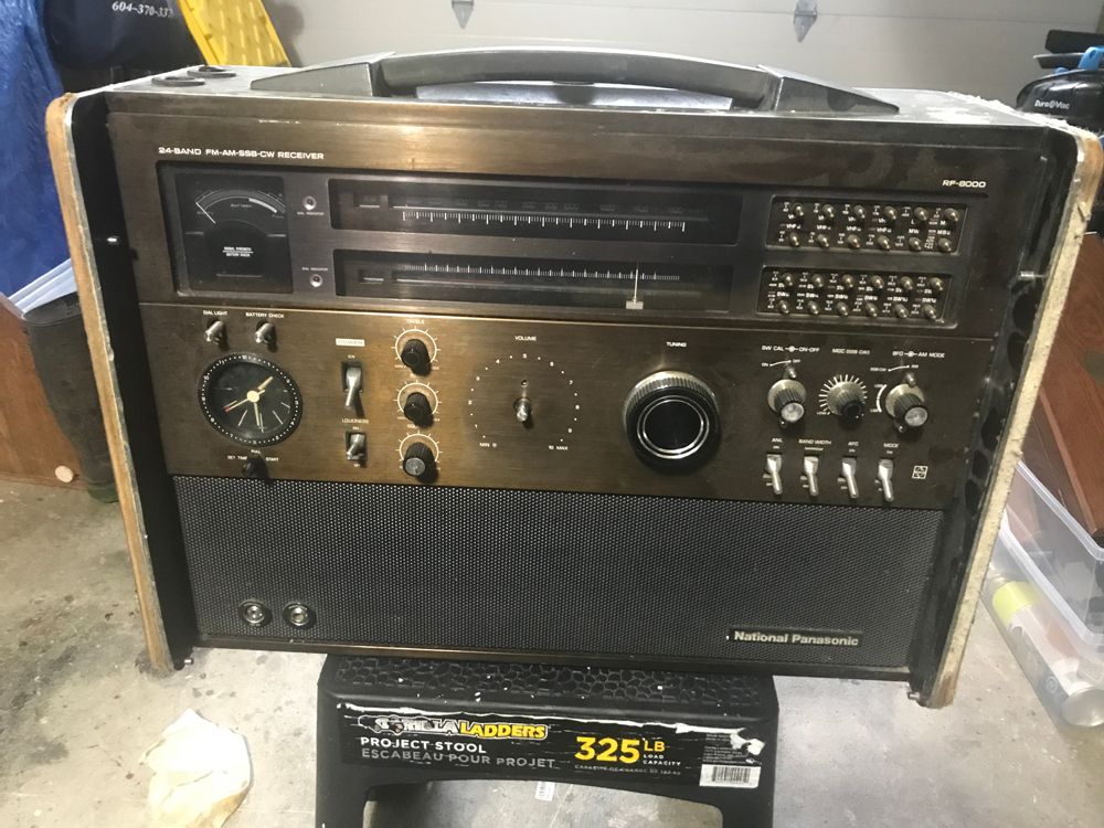
THE OVERVIEW UPON RECEIVING THE UNIT:
The negatives:
1. Evidence that someone had been inside the radio.
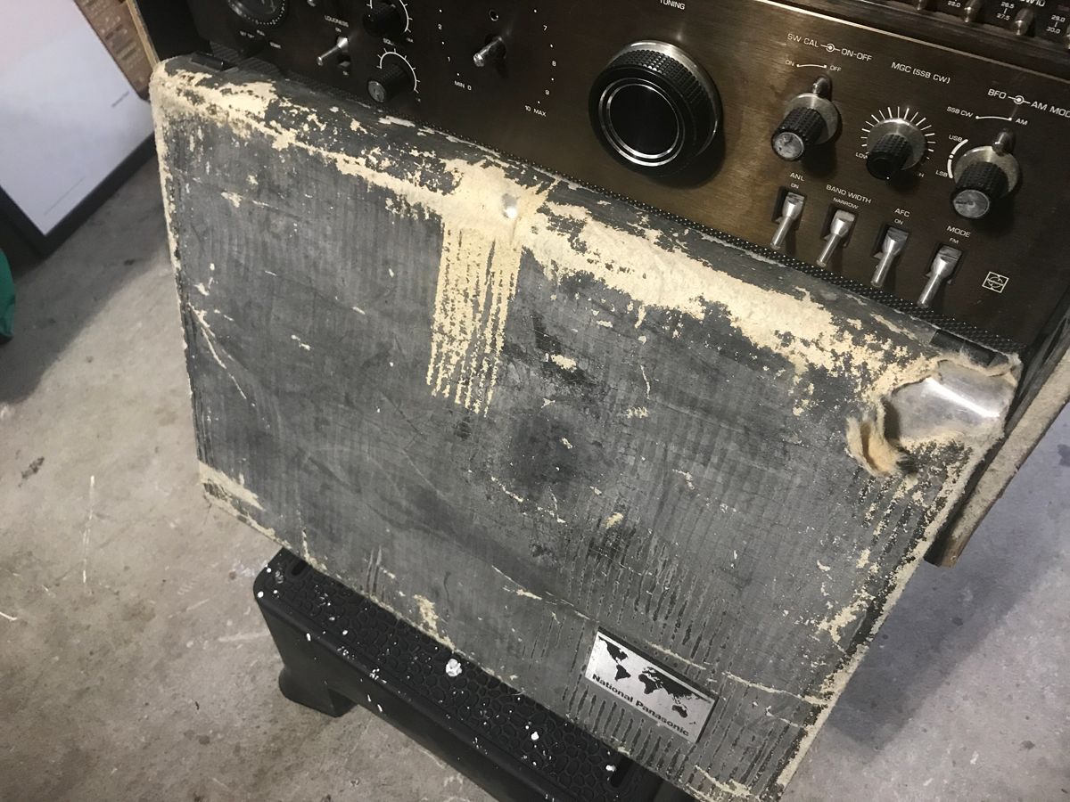
2. The cabinet Tolex covering was completely disintegrated.
3. The battery compartment cover has been broken at 3 of the 4-screw lock down points.
4. Missing volume knob.
5. Frozen volume pot.
6. Missing VHF pointer.
7. Could not tell if the dial string was present, broken or removed.
8. One of two telescoping antenna broken above base section.
9. Missing square antenna.
10. Clock was non-functional
11. Tuning selector system would not select correctly and drum would keep turning until power selected off. Only occasionally would the correct band be selected.
12. Definite mild nicotine smell and residue on external surfaces.
13. Internally some grounding straps were not secured.
14. Some wires were not connected to connectors (luckily it obvious were they belonged).
15. There are seven lights of which four are burnt out.
16. The four feet were hardened and rotted/chipped.
The positives:
1. The radio reception, clarity and sound were excellent, once I figured out how to temporarily work around the nonfunctional band selection system.
2. No battery residue.
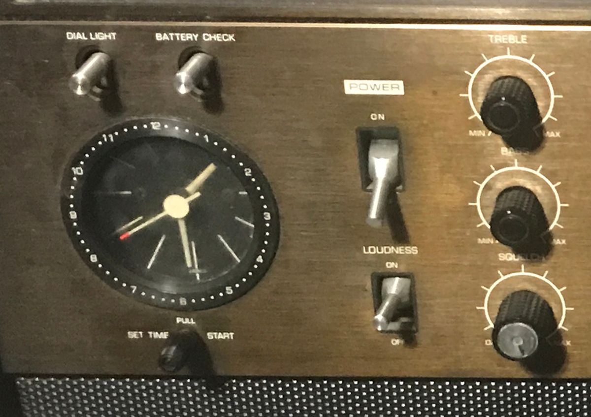
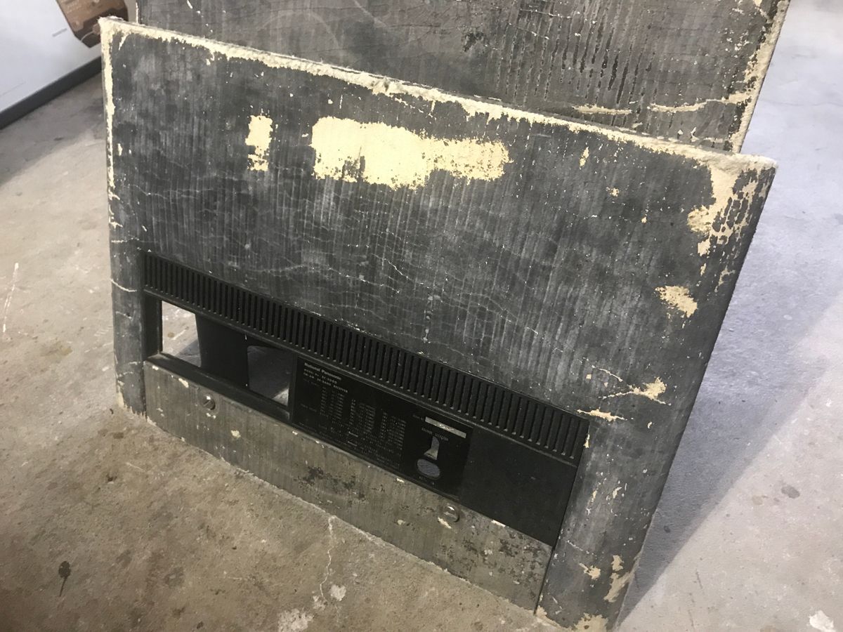
3. Facia plate and silk screening in excellent shape.
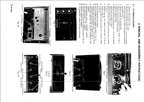
THE RESTORATION:
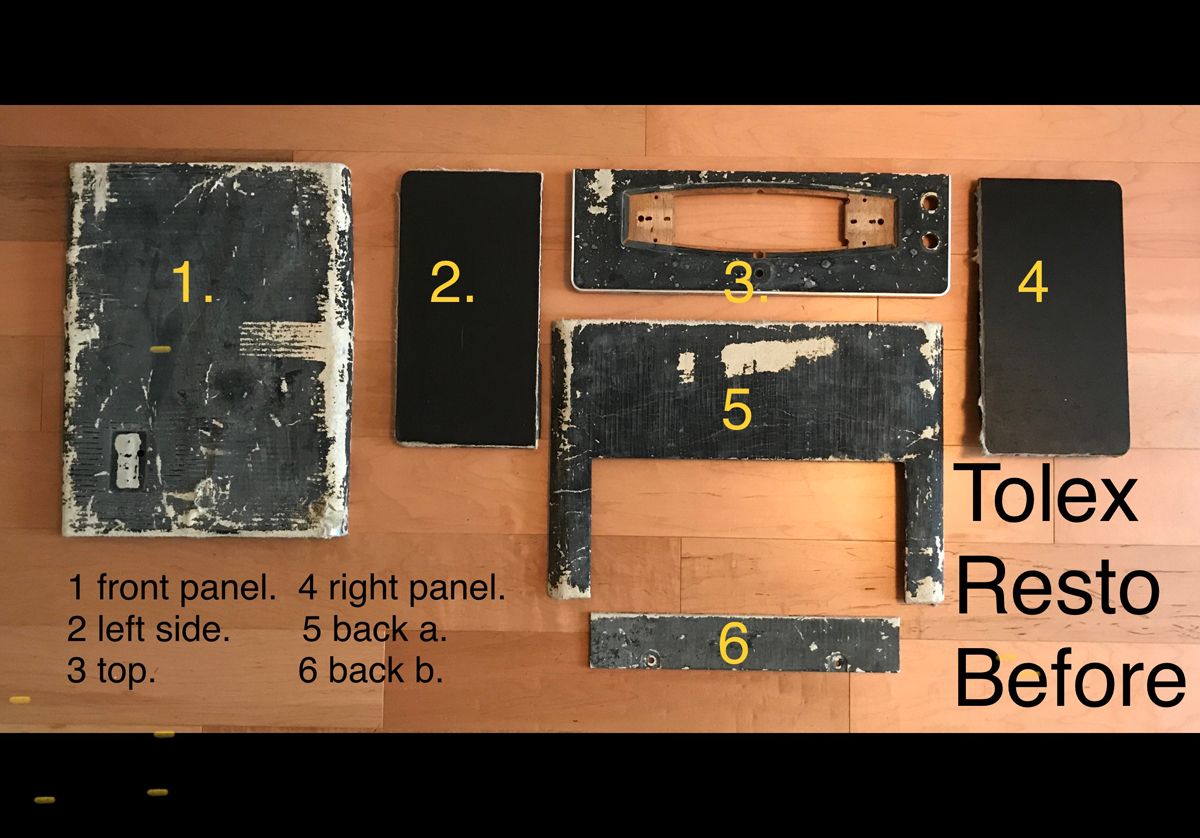
The cabinet:
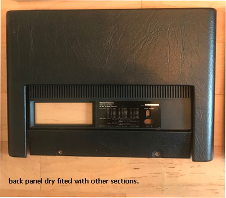
- rear cover:

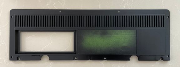
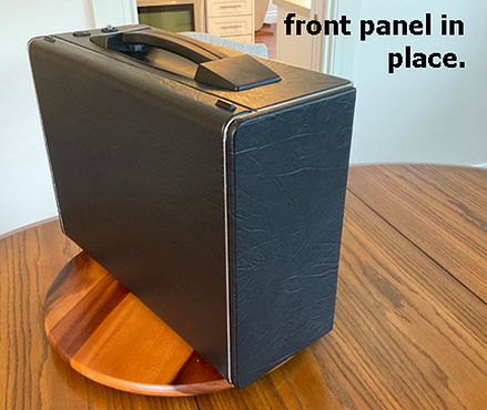
- front removable cover:
- top:
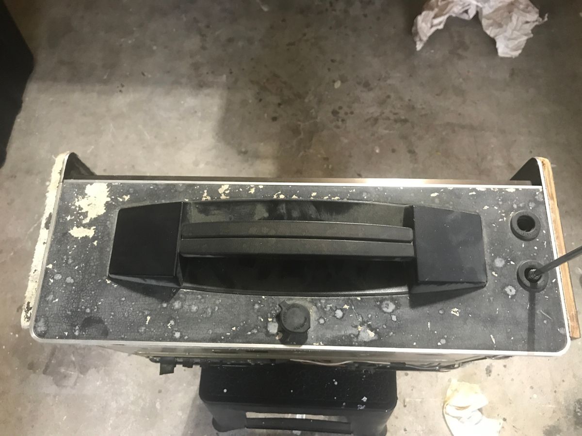
- all the tolex covering required removal and replacement:

Just some of the screws bagged and labled. Over 23 ziplock bags in total: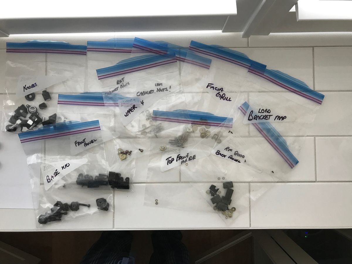
The cabinet suffered the most wear with complete degradation of the Tolex covering. It is composed of wood (Mahogany?) and aluminum components. The front facia covering is thick aluminum and was dented at one point which caused the top edge to be warped. The sides and back are wood. Metal brackets on the interior secure the panels in place. The cabinet has been disassembled and is being re-covered in Tolex. All screws were placed in labelled Ziplock bags with their origin and location marked for easy assembly. At one point there were over twenty five labeled bags!
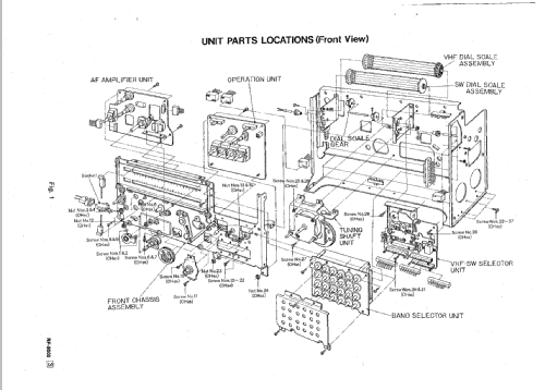
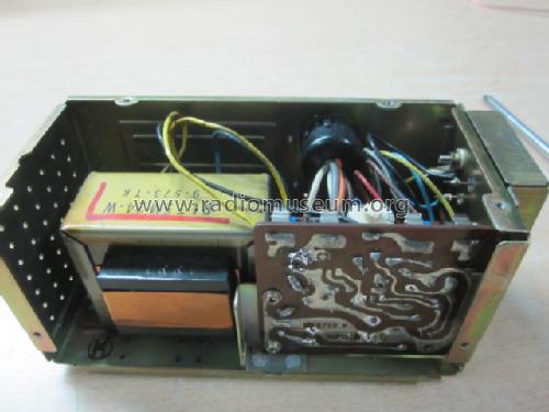
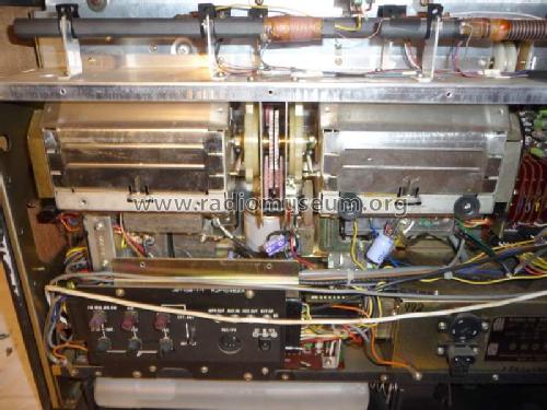
The chassis:
Still in cabinet:
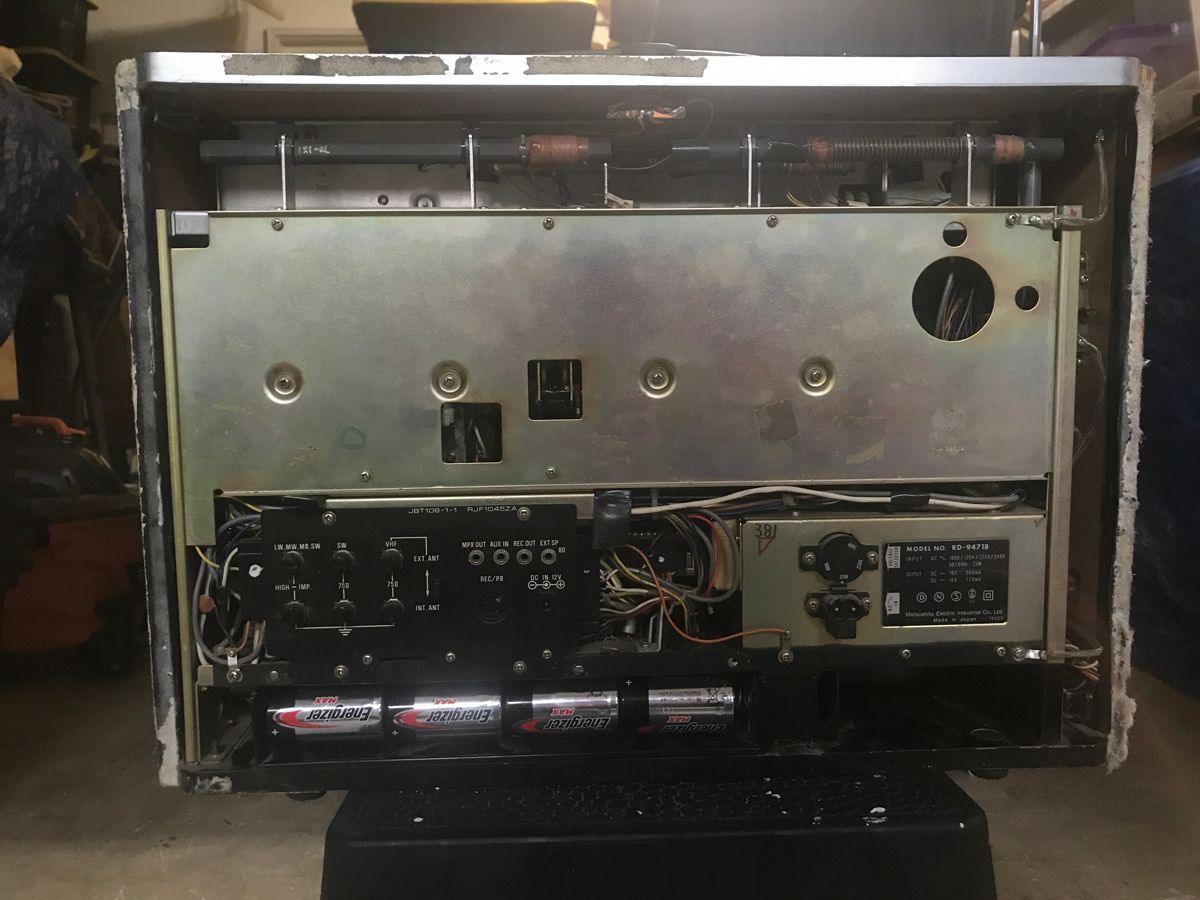
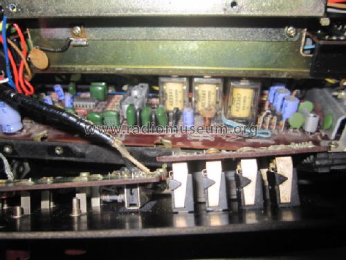
Connectors:
The main components of the radio were pin and socket connections. These as it turned out were contaminated by a smoking environment (nicotine goop) and suffered poor connections.
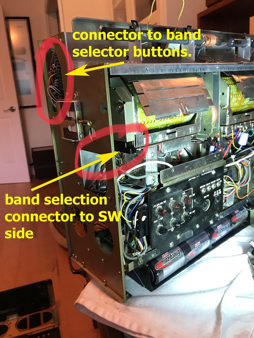
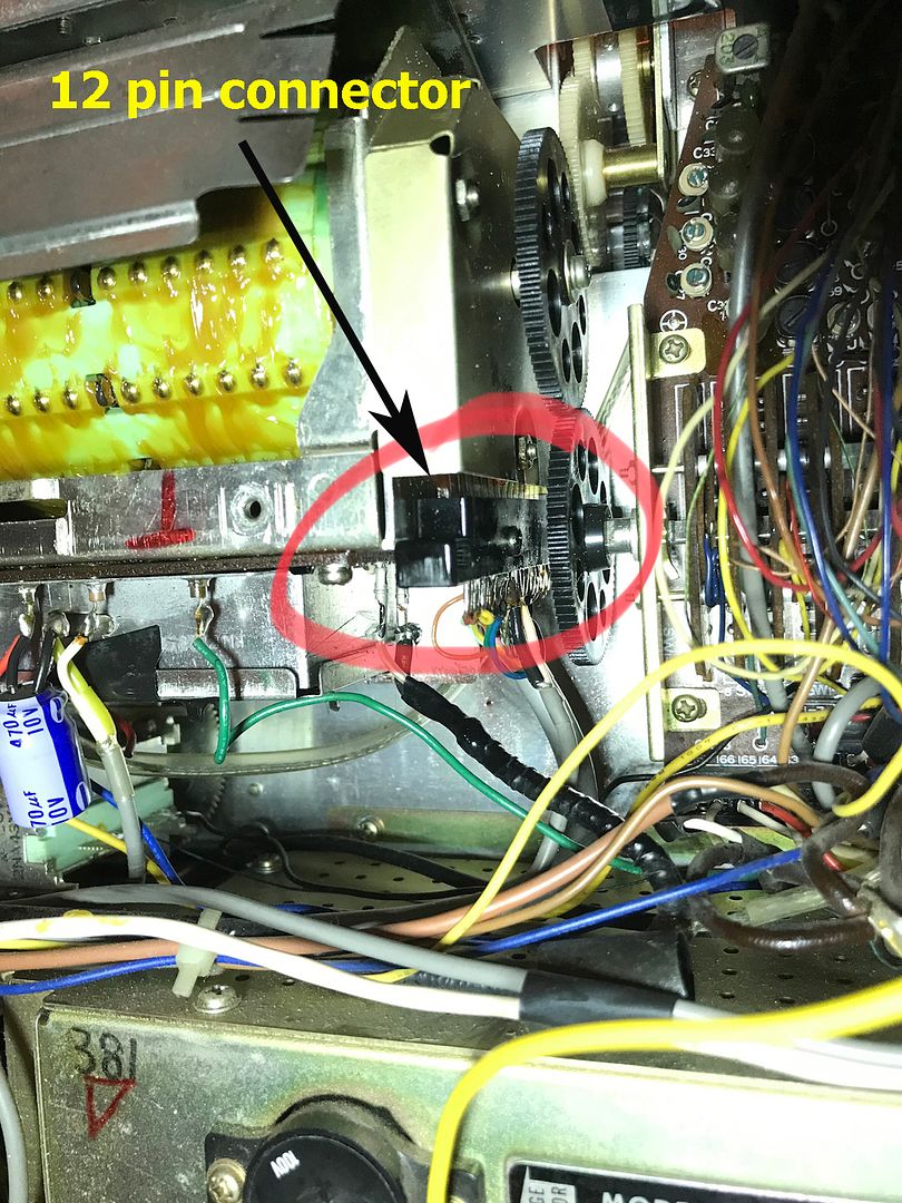
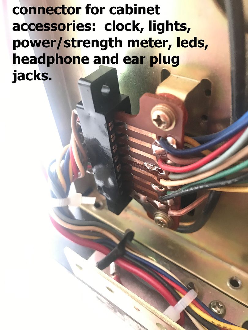
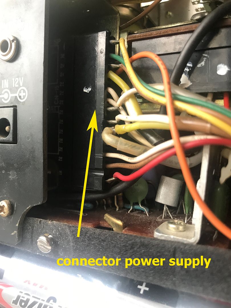
The connectors were all unplugged and both the female connector prongs and the male connector pads on the PCAs were cleaned with 1500 grit sandpaper and fiber brush. The newly exposed surfaces were cleaned with contact cleaner and the preserved with De-Oxit gold. As mentioned the overview above, cleaning of the connectors resulted in the perfect operation of the band selection mechanism. The band selection mechanism comprises of the VHF, SW and band selector button connectors.
All other plugs were also cleaned and treated with De-Oxit.
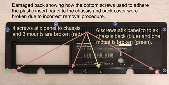
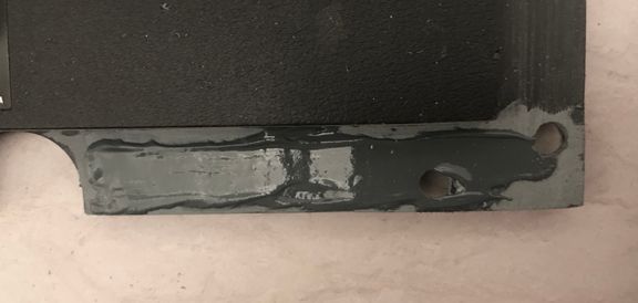
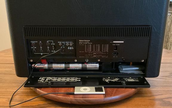
The rear panel battery hatch:
The battery cover has an access panel built in. The securing panel is attached at four points by screws. The panel screw attachment points were cracked and some missing. Repairs and reinforcements to the panel will be made by excising the damaged areas and replacing the plastic to allow for the screws to again secure it to the cabinet.
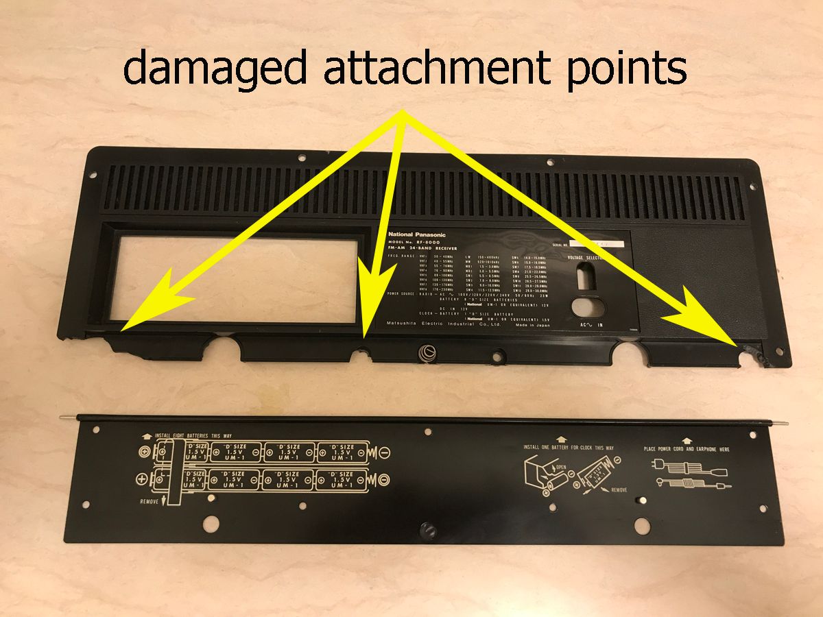
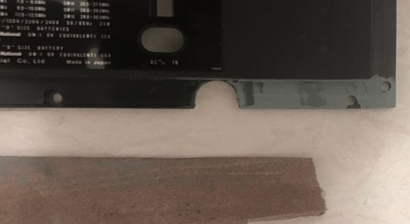
Some shots of the back plastic battery access cover. The cover was broken in three places, all involving screw hole locations Looks like someone tried to remove the panel with a tool and broke the screw attachment points:
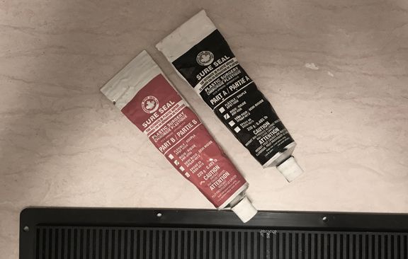
Picked up an automotive plastic replacement epoxy. This stuff is incredible as it can be milled, and holds, feels like the original plastic:
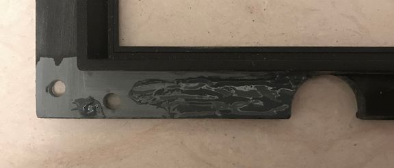
I had to prepare the plastic cover to receive the plastic epoxy:
I added the plastic epoxy to the affected areas and sanded, then added more until I had a flush finish on both sides:
On the back of the panel, the part hidden from view, I added aluminum strips from a clip board. Shaped these to reinforce the attachment points. Then drilled the holes for the mounting screws and lock down bolts:
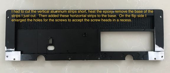
After epoxying the aluminum in place, drilling the holes, I cleaned and sanded the back and then painted in flat black, the original colour of the panel:
I drilled recess holes in the plastic epoxy to allow the screws to recess into the panel and thus allowing the plastic insert and attached metal battery access panel to fit flush with the rear tolexed cabinet:
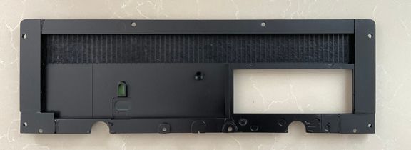
The panel was masked and painted on the visible side with mat black spray paint:
Here is a photo of the finished panel with screws in place to check for a correct recess:
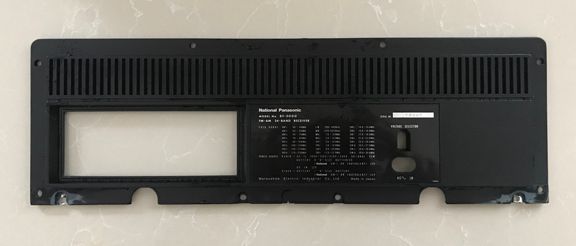
And the final product attached in place on the completed reassembled cabinet:
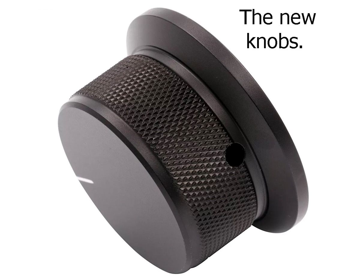
Volume and Tuning knobs:
The volume knob is missing. It was lost in an attempt by the previous owner to gain access to the volume pot shaft which had been seized at mid volume. The volume and tuning knobs will be replaced since an OEM volume knob is not available. These knobs are solid aluminum with screw anchors and are engine turned. Aftermarket solid aluminum knobs have been secured, but a bespoke reproduction of the missing knob is being turned to match the existing one in every detail. Still awaiting the results. Until then some aftermarket knobs were secured.
Frozen volume pot:
As stated in the overview above; the volume pot shaft was seized leading to the removal of the volume knob and its loss. The volume pot was removed, soaked in penetrating oil and cleaned. The fader was treated with De-Oxit green and the shaft and collar lubricated. It is fully functional now. It seems that the collar and shaft had corrosion which ‘welded’ the two together. The previous owner tried using pliers to turn the pot and a screwdriver inserted into the slot at the top of the shaft. This resulted in a scarred shaft which needed to be filed and sanded back to round.
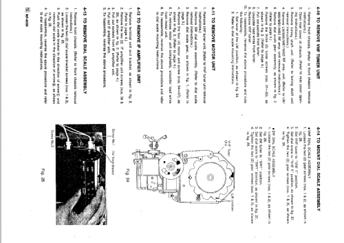
Missing VHF pointer:
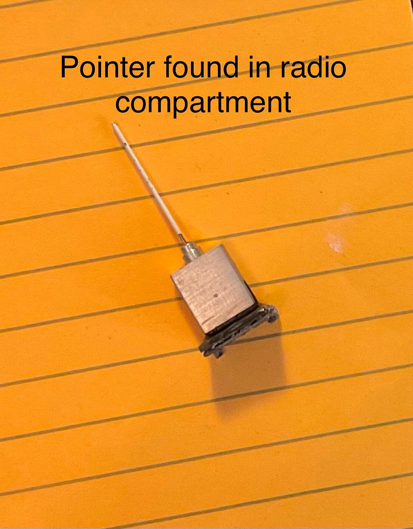
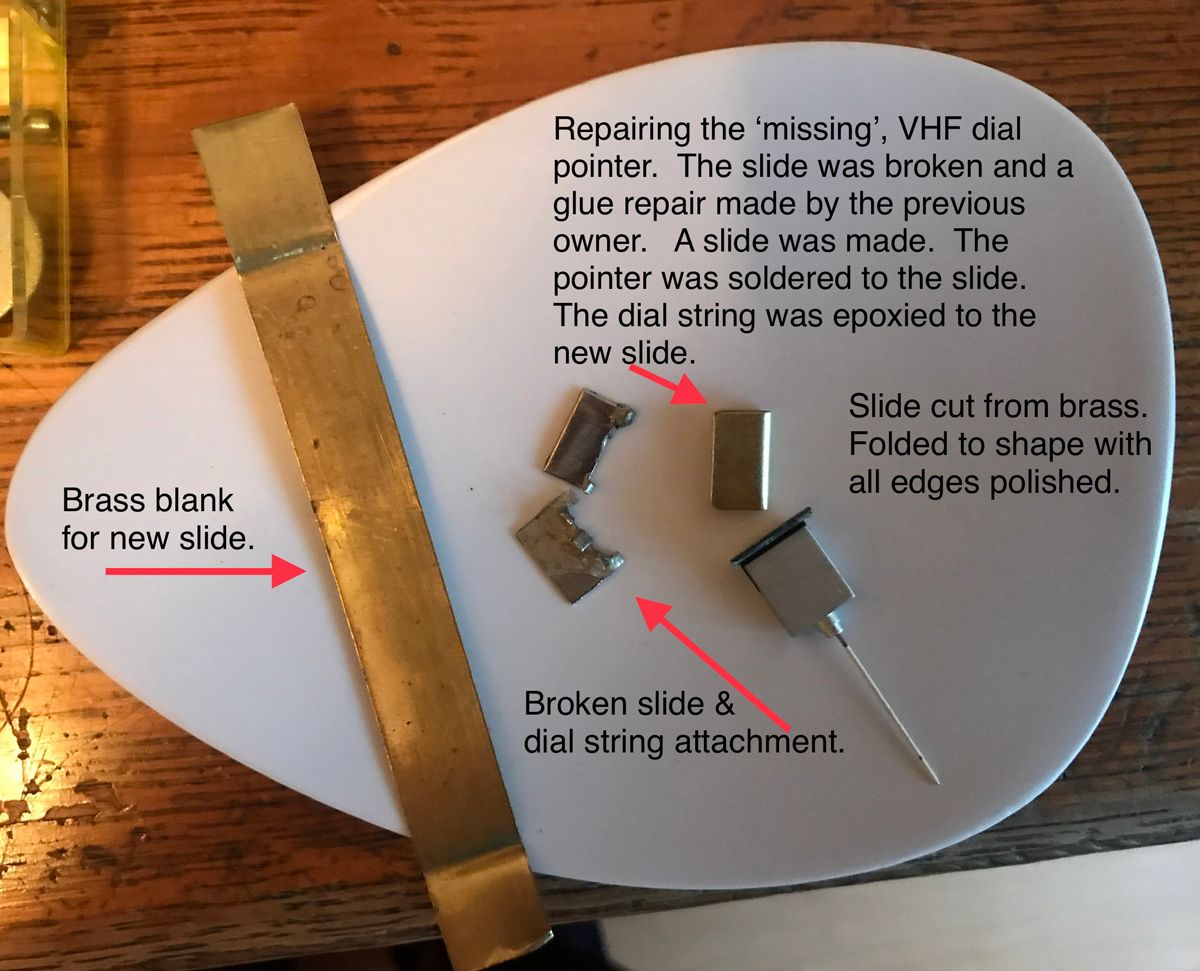
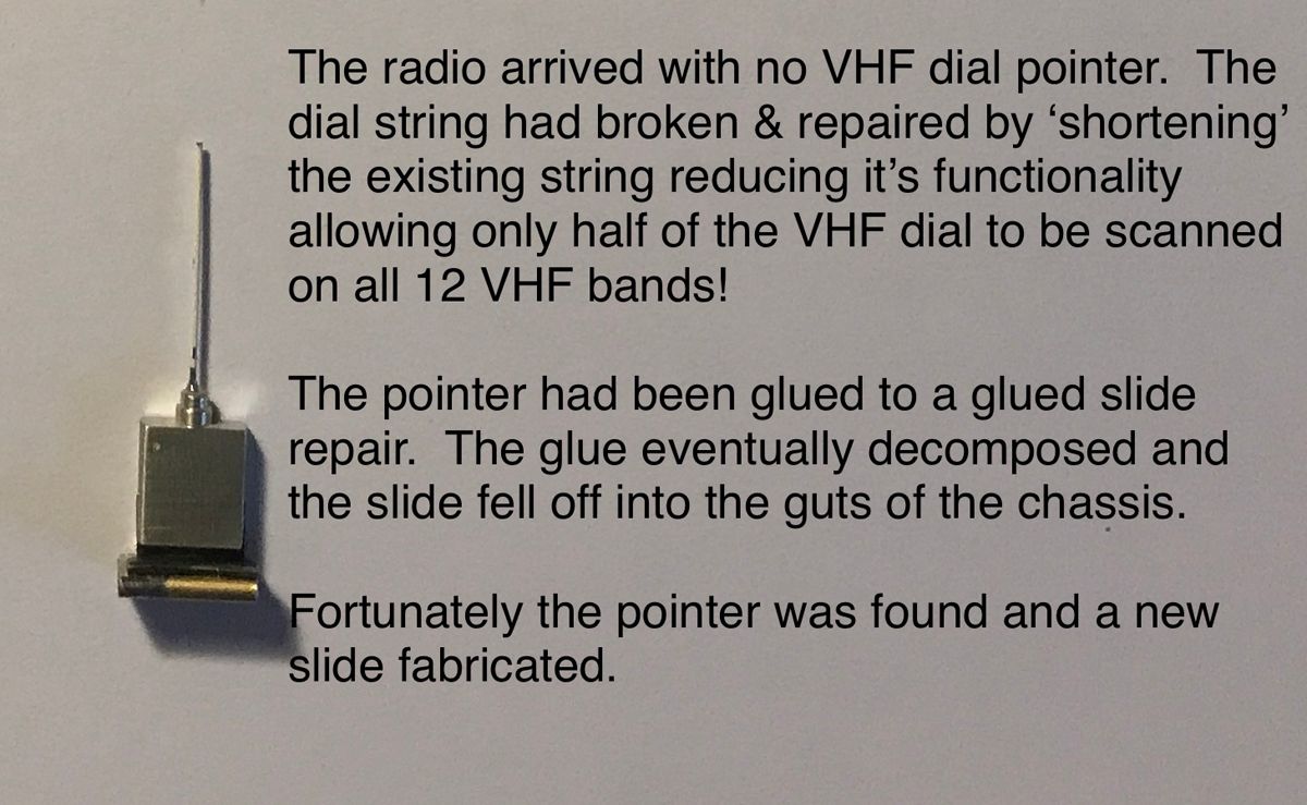
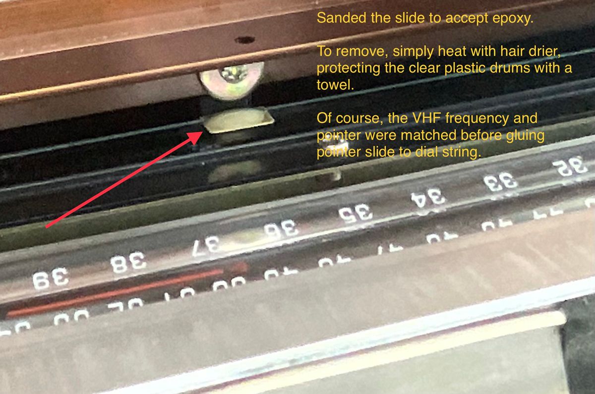
Fortunately, when the chassis was removed from the cabinet the pointer was found! It is complete and only needs to be re-attached to the dial string. Glue removed from bodged fix by previous owner. New slide fabricated, with all edges rounded, smoothed and polished for easy sliding. Pointer touched up with white paint and VHF dial pointer installed. Frequency matched to pointer position and dial string then epoxied to the dial pointer.
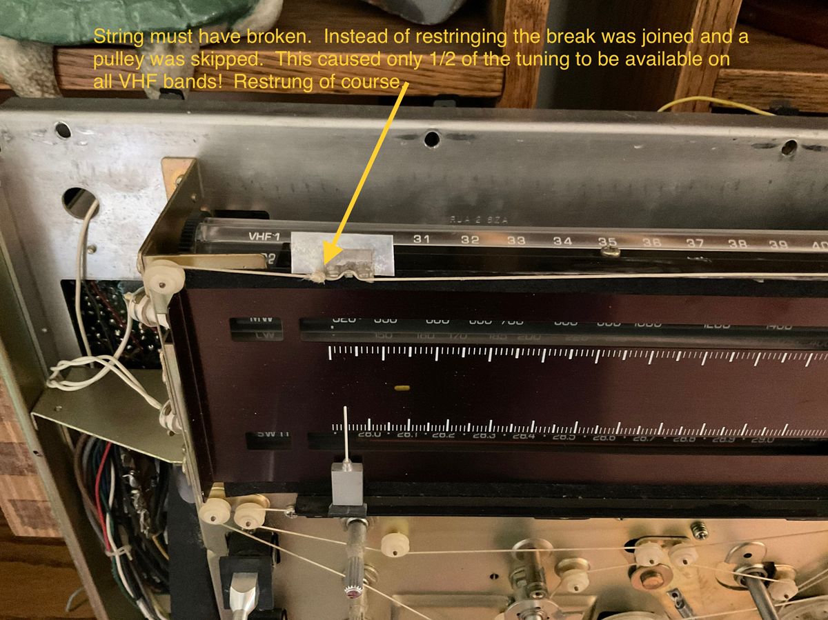
Dial string on VHF circuit
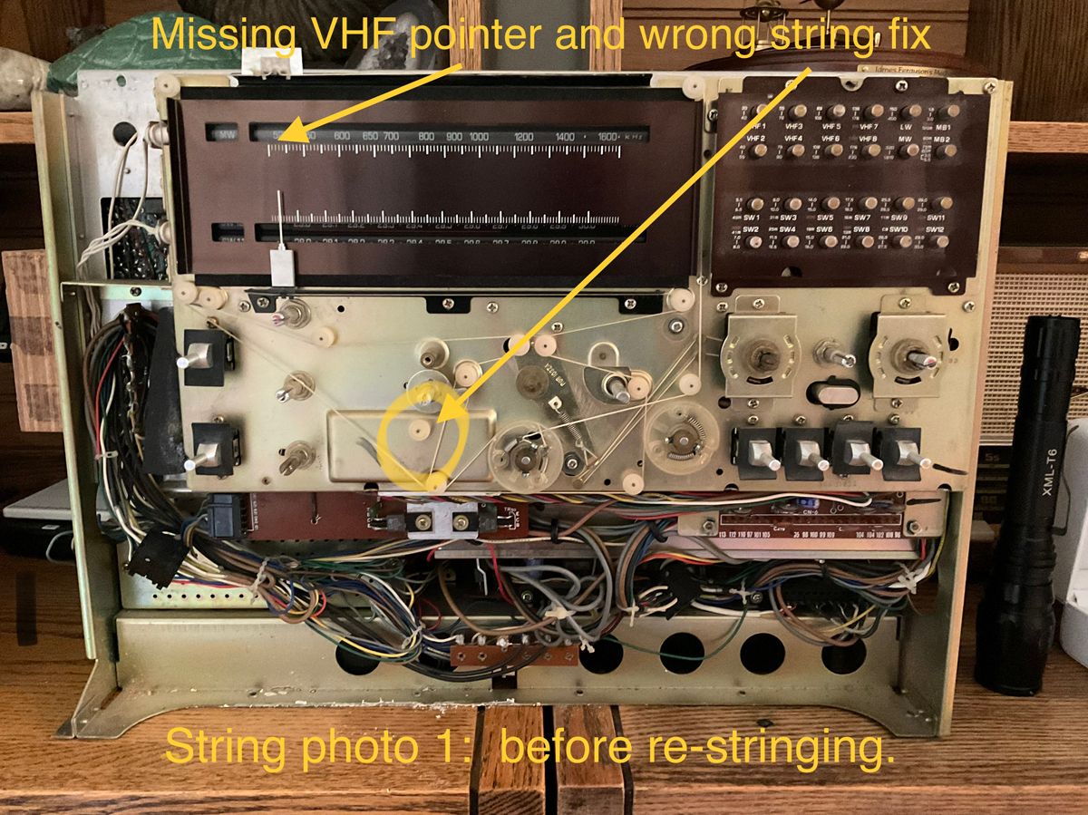
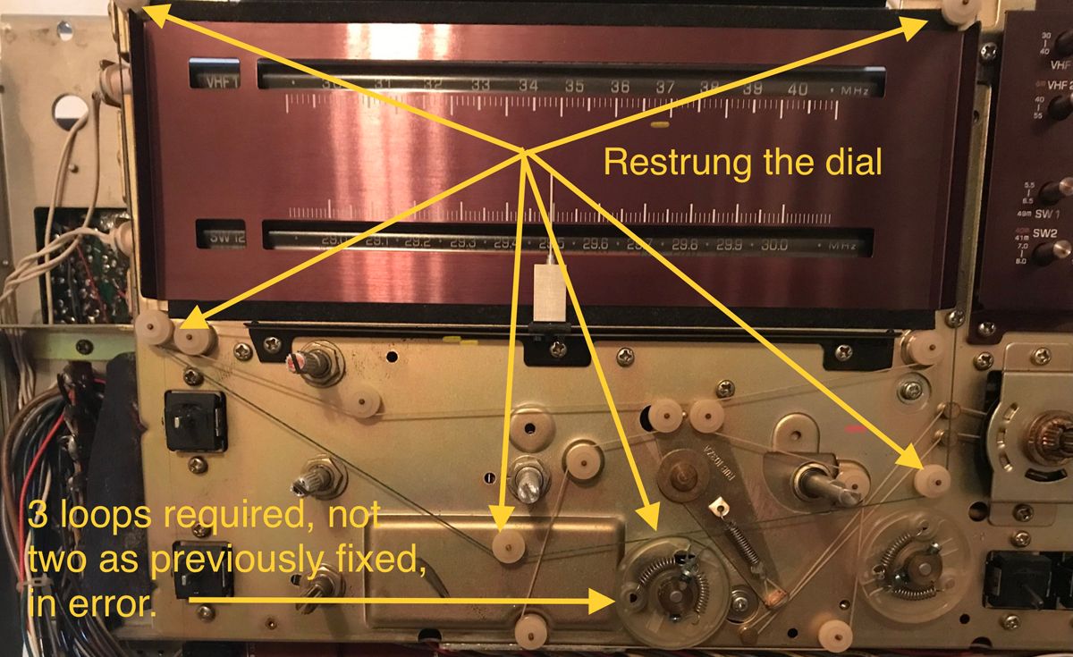
The dials string was intact. However, it was a bad fix by the previous owner. The dial string broke at the dial pointer mounting point. Probably the pointer jammed and to free it the tuning dial was turned to the point that the dial string broke. Someone gained access to the dial string. Their fix was to unwind one turn from the dial pulley and bypass one string pulley. This allowed enough string to knot and then the dial pointer was glued to the string. The glue let go and the dial pointer took up residence between the front of the chassis and facia plate. By reducing one turn on the dial pulley the ability of the VHF tuning range was reduced by half on all twelve VHF bands! Of course, this was not discovered until after the chassis was pulled. The VHF system was restrung. A new dial pointer clamp will be fabricated and the original dial pointer will then be installed as per factory design. All VHF bands are fully tuneable now.
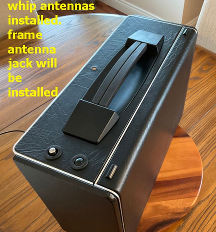
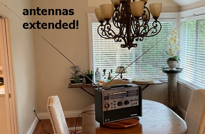
Telescoping antenna:
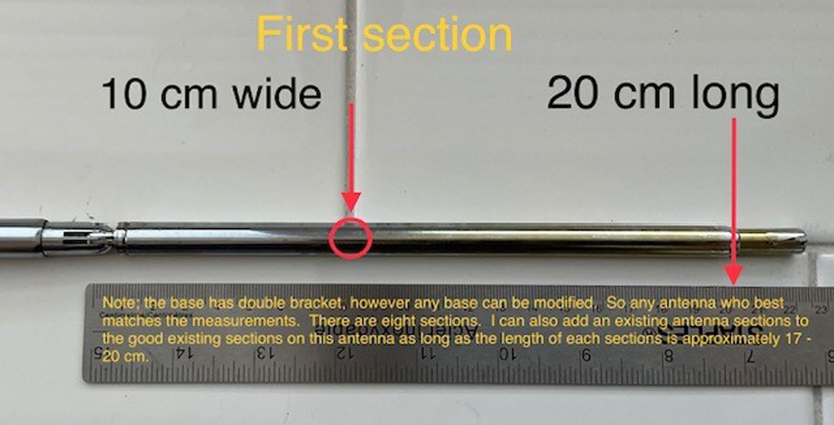
One is broken above the base. This means the ‘screw on portion’ needs to be secured. Searching for the appropriate replacement.
Still looking for a push button original antenna. (Update: may have found two originals!)
Until then, I replaced the missing sections of the broken antenna and used Shapeways to print 4 black bronze antenna caps. After measuring the original complete antenna (there are two) cap I reproduced these on a 3D print file. These caps are solid metal as the 3D printed plastic were too soft to tap and die. I drilled a hole in the cap and tapped it. I then threaded the top of the repaired antenna; the last solid section. This allowed the cap (with Loctite) to be screwed onto the last section. It is a darn close match to the discerning eye.
the caps as received from Shapeways. They are black bronze. One was sanded and shaped a little better then received:
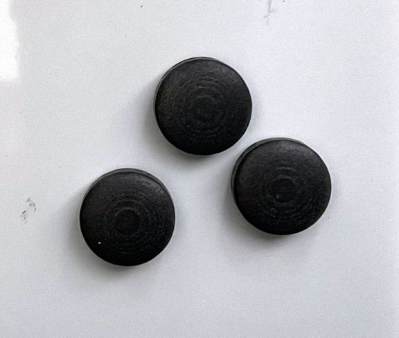
The cap on the upper antenna is the replacement and is also the one that was repaired. It does not have the push button system as in the original as that is incorporated into the section that was missing:
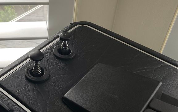
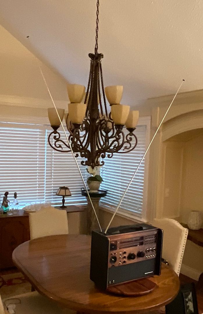
And the antennas fully extended:
Missing square antenna:
A new square antenna will be fabricated using appropriate gauge stainless steel and correct jack. A 3D printed connecting block will be created.
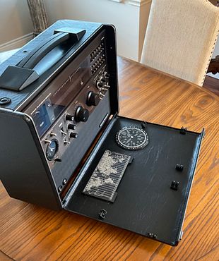
The clock: now this was fun because another hobby is watch and clock restorations!
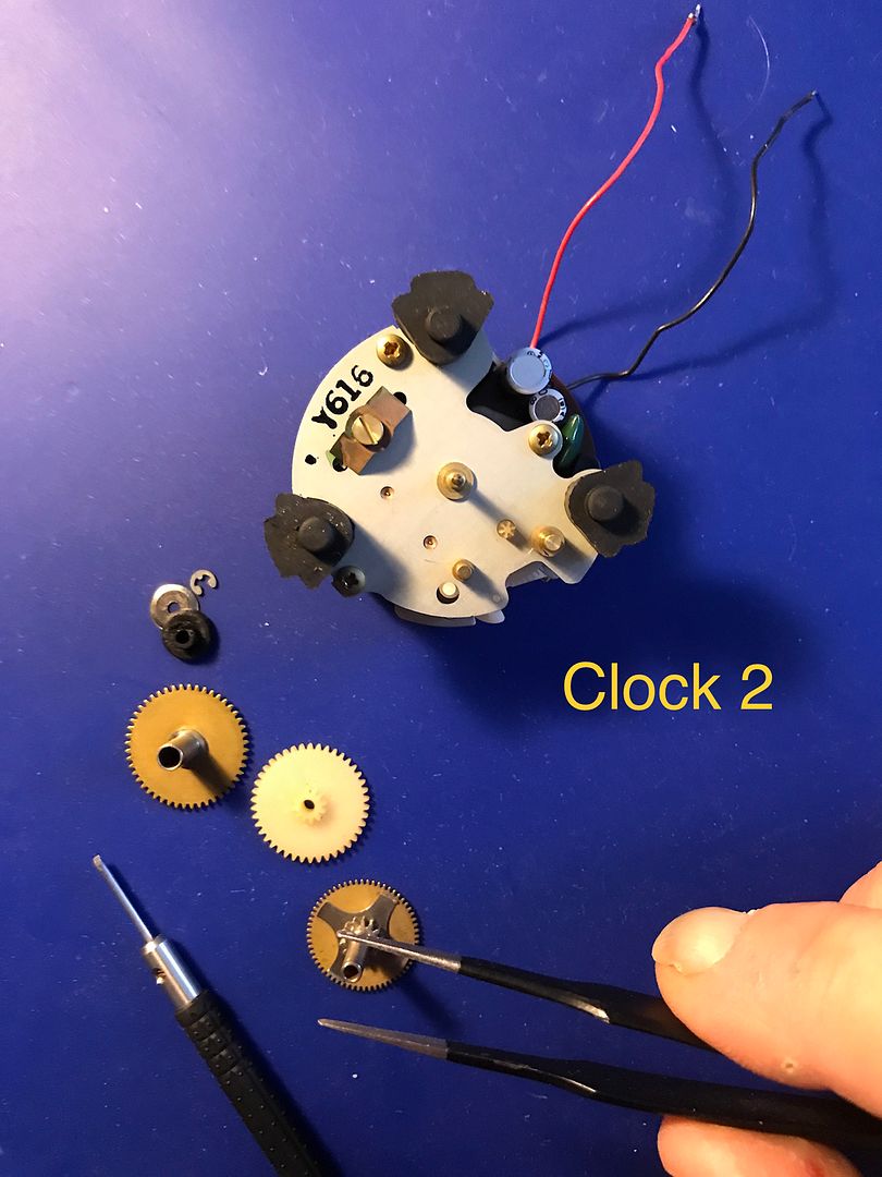
This is an interesting clock by JECO LTD. A Japanese company that made single legged tuning fork movements under license from Bulova. The tuning fork does not directly engage the driving gear as does the Accutron watch movement. It instead, excites the driving wheel into spinning at 300Hz. This in turn drives the gearing resulting in a smooth movement of the sweep second hand. In fact, the sweep second hand can spin in the opposite direction without harming the movement. One can induce the anti-clockwise motion by imparting a spin in the drive wheel opposite to the normal spin and then applying power to the circuit. The voltage for the movement is derived from a single 1.5v ‘D’ cell residing in a separate battery compartment.
The clock on this radio the was not functional. The clock was removed from the internal side of the facia plate. 1.5 volts was applied to the +ve and -ve wires which resulted in a 300Hz hum but no movement of the gears. Since the tuning fork is not physically engaged to the gears the hum confirmed that the oscillating circuit was functional. The oscillating circuit is composed of a coil, transistor, resistors and two capacitors.
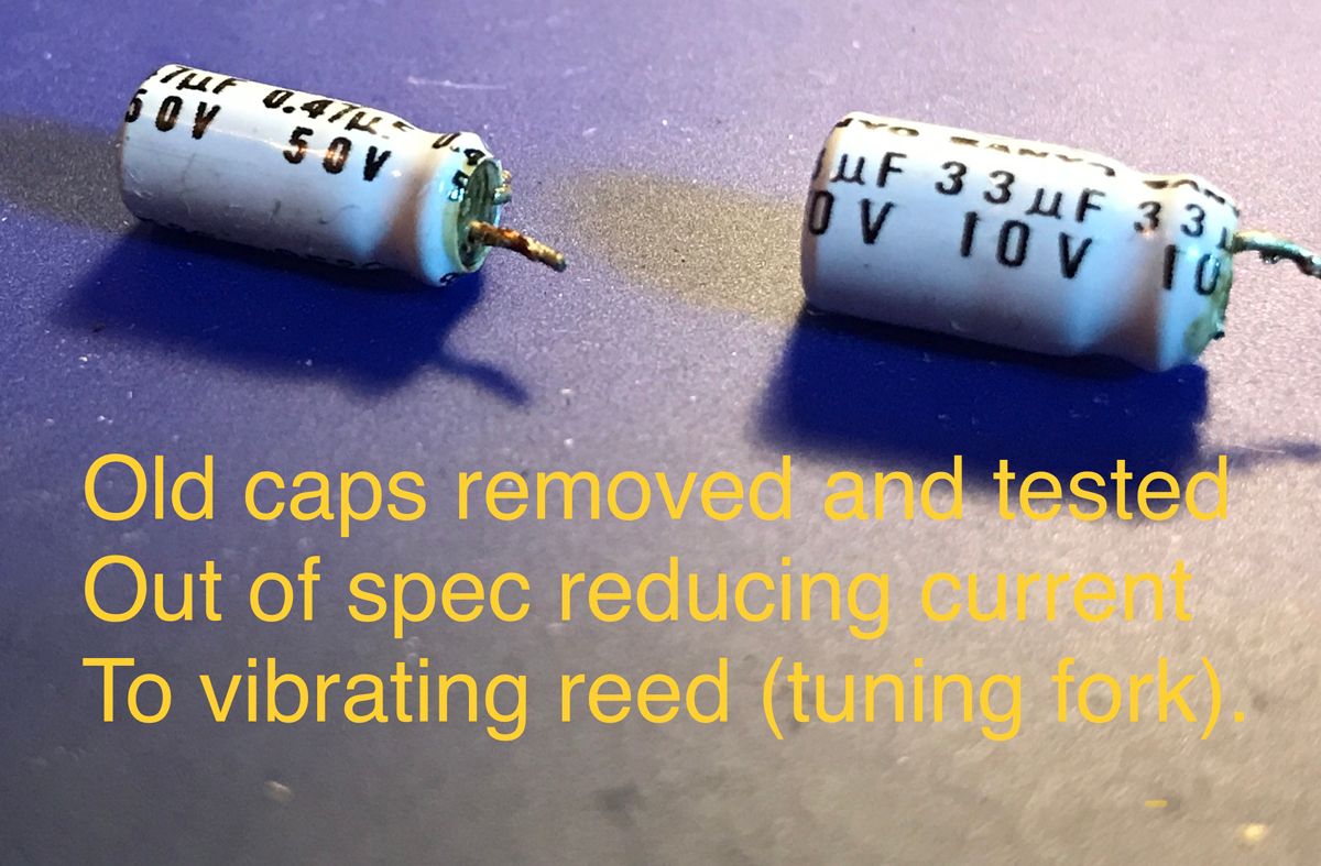
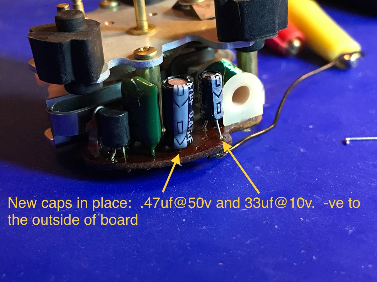
Both capacitors were removed and tested out of specification. They were replaced with equivalent new capacitors of 33uf @ 10v and .47uf @ 50v. This resulted in a much louder and more vigorous hum, but still the movement would not function. This indicated the pivots were worn or the oil had gummed up and seized the gear train. Fortunately, it was the latter.
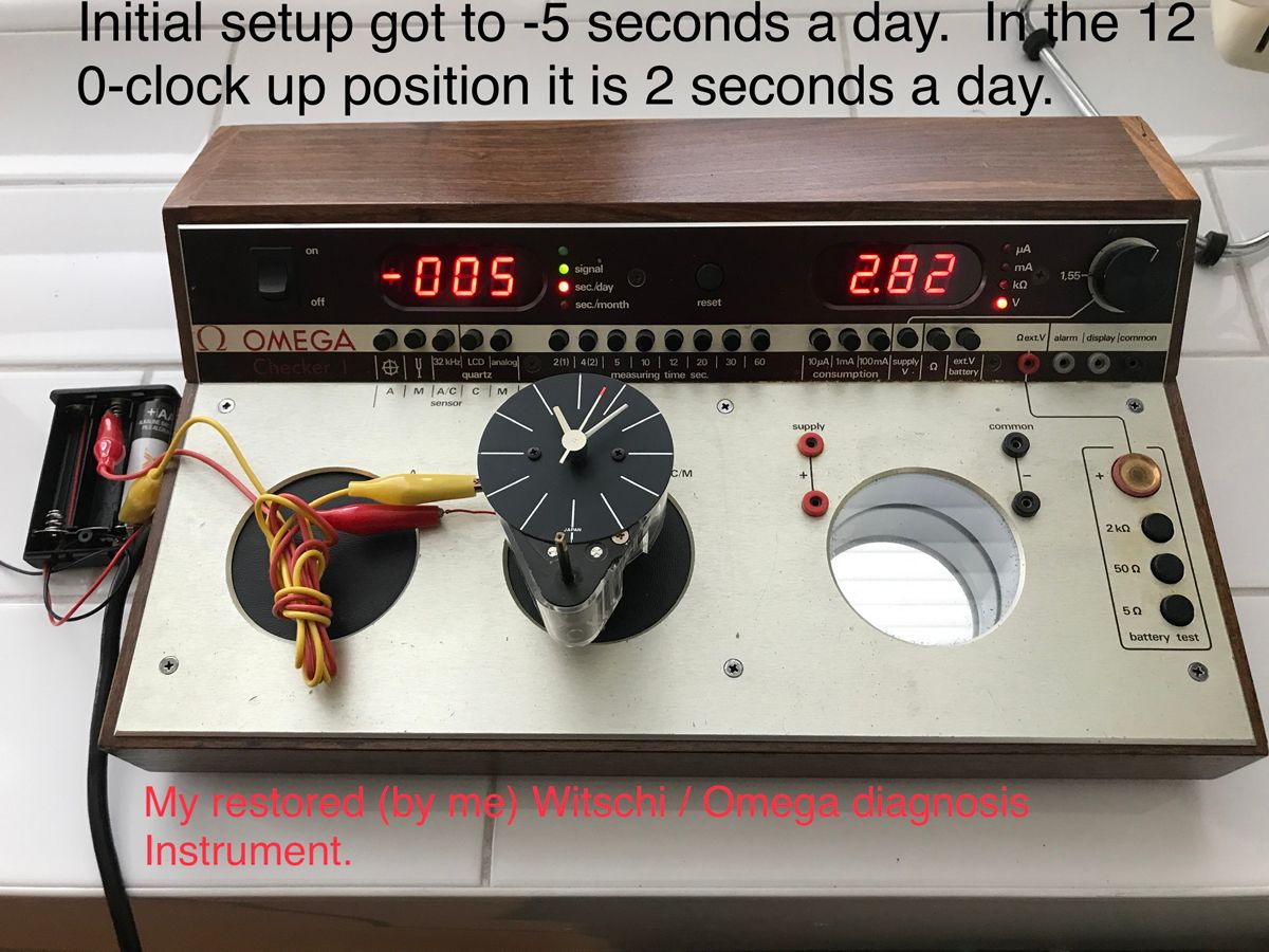
The movement was disassembled, the pivots inspected and were not worn. Oiled with Moebius 9010 oil on all pivots. Time setting gears were cleaned and greased. The circuit board was washed in IPA 99% and then preserved with De-Oxit gold applied uniformly with a paint brush.
It functions now to within -5 seconds a day. A very respectable rate clock considering its age.
and so far that is all she wrote! Awaiting the square antenna and the new volume knob. I will post then but until then, the radio is complete, fully functional and an extremely sensitive radio. It is back in reconditioned tolex cabinet.
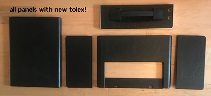
well the Tolex recovered panels have arrived and wow!
lets start with a before and after:
PANELS BEFORE:
PANELS AFTER:
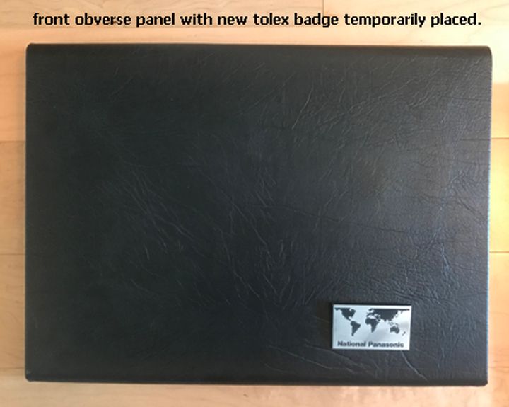
FRONT PANEL BEFORE:

FRONT PANEL AFTER:
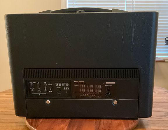
REAR PANEL BEFORE:
REAR PANEL AFTER:
VIEWS OF THE CHASSIS IN THE CABINET. (A little out of order here as the antenna has a new black matching cap added from a bronze 3d printing):
I have to mention, this weighs 50 pounds! I am sure that most of that are the screws, nuts, washers and etc.
Geoff Quickfall, 03.Feb.23