Oscilloscope 515A
Tektronix; Portland, OR
- Country
- United States of America (USA)
- Manufacturer / Brand
- Tektronix; Portland, OR
- Year
- 1957–1971
- Category
- Service- or Lab Equipment
- Radiomuseum.org ID
- 99151


Tektronix Catalog


Click on the schematic thumbnail to request the schematic as a free document.
- Number of Tubes
- 33
- Wave bands
- - without
- Power type and voltage
- Alternating Current supply (AC) / 105-125; 210.250 Volt
- Loudspeaker
- - - No sound reproduction output.
- Material
- Metal case
- from Radiomuseum.org
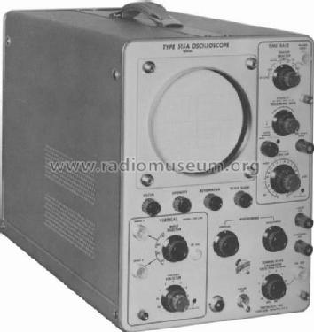
- Model: Oscilloscope 515A - Tektronix; Portland, OR
- Shape
- Tablemodel, high profile (upright - NOT Cathedral nor decorative).
- Dimensions (WHD)
- 9.75 x 13.5 x 21.5 inch / 248 x 343 x 546 mm
- Notes
- Röhren teilweise mehrfach vorhanden. Bandbreite 15 MHz.
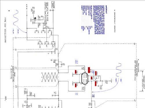
5-inch service scope. T55-P31 standard supply CRT, 4KV accelerating potential, DC to 15MHz passband, 0.2 usec/cm to 6 sec/cm sweep range in 22 steps, x5 sweep magnifier.
Depending upon the S/N, 6DJ8 tubes replaced some 6U8 and 6AN8 types in the time base section. Also 3 selenium bridges in the power supply were replaced by 12 silicon diodes from S/N 4030. A T-12G germanium diode added to the trigger circuit from S/N 4804.
- Net weight (2.2 lb = 1 kg)
- 18.1 kg / 39 lb 13.9 oz (39.868 lb)
- Price in first year of sale
- 800.00 $
- Source of data
- - - Manufacturers Literature
- Mentioned in
- -- Original-techn. papers.
| Tektronix 515/515A Instruction Manual (scan by courtesy of F.Novelli) | 5234 KB |
- Documents regarding this model
- Author
- Model page created by Pius Steiner. See "Data change" for further contributors.
- Other Models
-
Here you find 388 models, 376 with images and 92 with schematics for wireless sets etc. In French: TSF for Télégraphie sans fil.
All listed radios etc. from Tektronix; Portland, OR
Collections
The model Oscilloscope is part of the collections of the following members.
Forum contributions about this model: Tektronix; Portland,: Oscilloscope 515A
Threads: 2 | Posts: 2
hello Emilio,
there was an update to change the selenium rectifiers by silicones.
I have uploadet a picture from my 515A where you can see this.
greetings
Martin

Attachments
- Tek 515A (117 KB)
Martin Mehlhose, 30.Oct.11
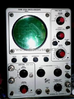
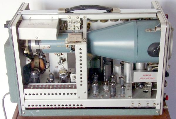
515A was a 5 inch portable oscilloscope introduced around 1959 as portable service instrument. Its single vertical channel, strange enough, had two UHF coaxial inputs, switched by means of a rotary switch on the panel. Probably two full channels would have affected complexity and cost, rising them at the same level of the plug-in mainframes. Even with this compromise, its price was very high, 800 US dollars in 1959: in those years for the same price one could buy a small flat. We can imagine that its users connected the two probes at two different test points and could select the waveform to display rotating the selector knob.
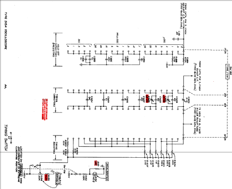
Its specs were quite impressive too. Vertical deflection bandpass was DC to 15 MHz within 3dB; risetime was under 23 nanoseconds. Time base went from 200 nanoseconds/cm to 6 seconds/cm in 22 calibrated steps; x5 magnifier extended fastest sweep rate down to 40 nanoseconds/cm. Internal trigger operated up to 15 MHz with as little as 2 mm vertical deflection. Its 5 inch flat screen CRT, type T55-P2 or P32, operated with 4KV accelerating potential. Other phosphors, P1, P7 or the high writing speed P11, were available as option.
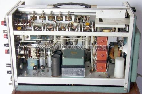
In about 13.5 kg. its circuits used 33 vacuum tubes, including the CRT, plus 11 neon bulbs, 3 incandescent lamps and 3 bridge selenium rectifiers, replaced by 12 silicon diodes from S/N 4030 upward. Even a T-12G germanium diode was used starting from S/N 4804 in the trigger circuit.
Servicing the 515A
In its manual Tektronix opens the section dedicated to the troubleshooting with the following sentences:
‘This is a complex electronic instrument. There is no simple way of locating troubles. With an understanding of the circuits, you will generally be able to localize the trouble just from front panel observations.’ Of course nothing is said about the difficulties of locating faults when no trace appears.
I found one of these oscilloscopes on e-bay for less than one hundred Euro. An early visual inspection evidenced that the rear filter was severely warped in the middle and the fuse had been removed. The first action was a general clean-up, with brushes and lint-free cloths. Then it was necessary to find a fuse holder cap compatible with the missing original one and to insert a new fuse.
The equipment had suffered a stroke in the rear cooling filter. As result, two out of the three fan rubber spacers were broken and the fan itself was hanging inside the cabinet from the third spacer. It was necessary to remove the entire fan cage, unscrew the rubber mounts, glue them with flexible cyanoacrylate and then reassemble the fan. Rotor bushings were cleaned from dried grease and lubricated. Careful aligning of the bent propeller blades was then performed. Cleaning and straightening of the bent air filter completed the job in this section.
 |
 |
Fig. 1 - Left, a broken rubber spacer near to the good one. Right, the fan just serviced.
After the usual reforming procedure at half primary voltage, sparks occurred inside the 6AQ5 EHT oscillator at power-on. The 6AQ5 was replaced with a new 6005 and the problem disappeared. Anyway no trace appeared and therefore further investigations were necessary as we will see below.
Caution! The operations described below involve measurements on very harmful high voltage circuits! Useful recommendations are:
- Always use suitable instruments. Modern multimeters and oscilloscope probes do not withstand high voltages found in these vacuum tube instruments. I used an AVOmeter 8 Mk IV, ranging up to 2500V, and a homebrew 10:1 voltage divider as probe for evaluating ripple in the power supply circuits.
- Connect the cables or the probe to the measuring points only when the power cord is unplugged. Do not attempt to touch them when power is applied to the oscilloscope.
- After power-off wait enough time to have capacitors discharged, before touching cables and hot components inside. This is especially true when power has been turned on for very few seconds, not allowing the electron emission build-up inside the vacuum tubes.
- Always use a silver loaded soldering alloy when replacing components from the typical ceramic strips.
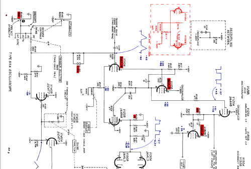
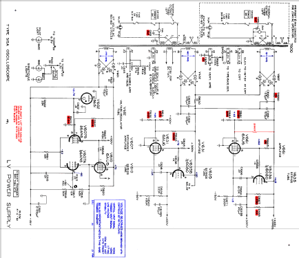
In the 515A all the voltages, -150, 100, 300 and even the 400 unregulated one, were found low. Since the regulated voltages are all referred to the –150 volts, the power supply service started from this section. The multimeter returned a voltage of about –145 volts on the filter capacitor, before the series regulator. A huge ripple was observed connecting an oscilloscope through a 10:1 voltage divider. The AC secondary voltage was correct, about 175 rms volts. The electrolytic capacitor C601, 125 uF at 450 VDC, was found almost entirely dried, the capacitance meter reading about 1 microfarad. In addition, all the three selenium rectifiers evidenced poor reverse resistance values. Almost certainly this damage, since involved all the selenium stacks, had been caused by improper power-on attempts by the dealer. In the feedback networks paper capacitors C613 and C666, both 10 nanofarads, were leaky and the leakage resistance, in the order of very few megahoms, could have impaired the precision of the associated voltage dividers.
Fixing of the supply section problems required the following actions:
1) The three selenium bridge rectifiers were removed and modified, replacing one metal washer per section with fiber ones, in order to open all the selenium diodes. Silicon diodes were then added in parallel to the old stacks. A finishing coating with a red nail lacquer completed the job.

Fig. 2 - Starting from left: A) Original selenium rectifier. B) 1/2 “ fiber washers for flexible water hoses are approximately the same size of the metal washers used between the plates in the stacks. C) Once mounted the insulating fiber washers into the selenium stacks, silicon diodes were soldered to the terminal lugs. D) After a lacquer coating, selenium rectifiers are back again, with their original look.
2) The electrolytic capacitor C601 was replaced with an good one, that had previously been preformed for about one hour, with 220 DC final voltage and the leakage current, monitored across a 100 kohms limiting resistor, stabilized to very few microamps.
3) C621, 10 nF, on the –150 V section and C666, same value, on the +300 volts section were replaced with new plastic film capacitors.
4) Calibration of the –150 volts output and check of the other voltages was then performed.
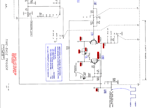
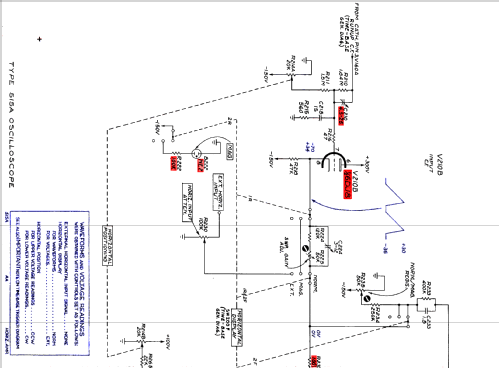
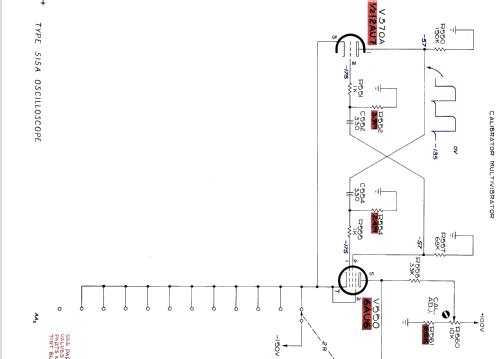
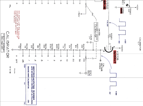
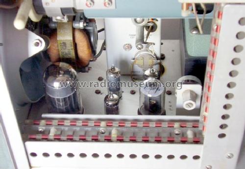
Once fixed the power supply, a small dot appeared on the screen, but time base controls were not operating. For this section the schematic diagram found on the Web was quite different from the actual circuit. Anyway, after several measurements along the chain and after a careful visual inspection with a magnifying glass, a cut wire was found between the Schmitt multivibrator of the trigger section and the time-base Miller integrator. I would like to know the guy who did this job!

Fig. 3 - The circle indicates the wire jumper that had been cut, insulating the time-base integrator from the trigger circuitry.
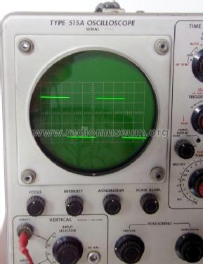
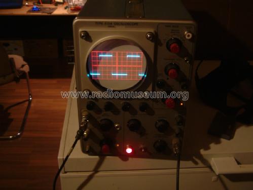
Once replaced the jumper, the oscilloscope returned to life with a sharp trace.

Fig. 4 - As result of the above steps, this was the sharp trace visible on the screen.
The electrical service terminated with a quick performance check of the internal calibrator and then of the vertical gain, of the trigger sensitivity and of the time-base precision.
As in many Tek scopes, the carrying handle was frayed. I spent a lot of time to find suitable materials, black leatherette and waxed white sewing cord, and more time to build a new handle around the old steel core. The result was quite poor, since the cord tension was not uniform.

Anyway today this little brother of the huge mainframes lives again, showing a very stable operation within its original specs.
 |
 |
 |
Emilio Ciardiello, 09.Oct.11