R1155 / R1155D
MILITARY U.K. (different makers for same model)
- Country
- Great Britain (UK)
- Manufacturer / Brand
- MILITARY U.K. (different makers for same model)
- Year
- 1940–1945
- Category
- Military Receiver
- Radiomuseum.org ID
- 93637


Thanks for Mr.Sik Béla Budapest, Hungary!

Thanks for Mr.Sik Béla Budapest, Hungary!
Thanks for Mr.Sik Béla Budapest, Hungary!
Thanks for Mr.Sik Béla Budapest, Hungary!
Thanks for Mr.Sik Béla Budapest, Hungary!
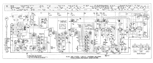
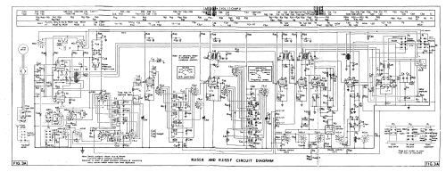
Click on the schematic thumbnail to request the schematic as a free document.
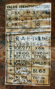
- Number of Tubes
- 10
- Main principle
- Superheterodyne (common); ZF/IF 560 kHz
- Wave bands
- Wave Bands given in the notes.
- Power type and voltage
- Powered by external power supply or a main unit. / AC: 6.3V; DC: 220 Volt
- Loudspeaker
- - For headphones or amp.
- Material
- Metal case
- from Radiomuseum.org
- Model: R1155 / R1155D - MILITARY U.K. different makers
- Shape
- Tablemodel, low profile (big size).
- Dimensions (WHD)
- 16.4375 x 11.375 x 9.375 inch / 418 x 289 x 238 mm
- Notes
-
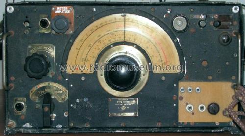
Receivers designed for use in military aircraft including the RAF Avro Lancaster bomber, with the T1154 transmitter. Also used in some ASR launches, radio vehicles and ground installations.
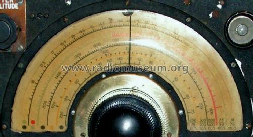
With 5 frequency ranges:
Range No : 1 (HF)
2 (HF)
3 (MF)
4 (MF)
5 (MF)18.5 MHz to 7.5 MHz
7.5 MHz to 3.0 MHz
1,500 kHz to 600 kHz
500 kHz to 200 kHz
200 kHz to 75 kHzType of wave: CW, MCW and RT
With magic eye tuning indicator, BFO and AVC, connections for headphones, aerial, Visual Indicators and the transmitter. With D/F (Direction Finding) and homing functions using type 1 Visual Indicators.
External power supply: HT 220V 75 mA, LT 6.3V 4A.R1155 (ref. 10D/98) : Aluminium case, weight 26 lb.
R1155D (ref. 10D/1331): Steel case, weight 32 lb.There are several other R1155 versions known.
- Net weight (2.2 lb = 1 kg)
- 26 lb 0 oz (26 lb) / 11.804 kg
- Mentioned in
- -- Original-techn. papers. (Air Ministry A.P.2548A (reprint Sept. 1947))
- Author
- Model page created by a member from A. See "Data change" for further contributors.
- Other Models
-
Here you find 152 models, 120 with images and 49 with schematics for wireless sets etc. In French: TSF for Télégraphie sans fil.
All listed radios etc. from MILITARY U.K. (different makers for same model)
Museums
The model can be seen in the following museums.
Forum contributions about this model: MILITARY U.K.: R1155 / R1155D
Threads: 2 | Posts: 3
Salve ai soci . Per la prova di questo ricevitore , mi sono autocostruito alimentatore e amplificatore valvolari , essendone il ricevitore sprovvisto.
Per provarlo ho voluto cominciare col collegare solo la tensione dei filamenti non vedendo accendersi questi ultimi , mi sono accorto che il cavo di collegamento che va dall'alimentatore al ricevitore era molto caldo , dopo aver tolto tensione , mi sono accorto che nn c'erano piu i 6,3 V all'uscita dell'alimentatore.
Dove potrei ricercare il guasto nel ricevitore ?
Saluti Gabriele
Gabriele Seccia, 19.Apr.14
RECEIVER MARCONI R1155 OVERVIEW
History
On order from the Air Ministry (AM), Marconi Wireless Telegraph Company in 1939 started the development of a transmitter/receiver system, the T1154/R1155, based on the AD77/AD6872 which was used in passenger aircraft. By that time Marconi was the leading manufacturer of aircraft radio in England and perhaps in the world. The system was intended for use in heavier military aircraft, and during the second world war it was used in light bombers like the Blenheim and Mosquitio, and in heavy bombers like the Stirling, the Halifax and above all the famous Avro Lancaster.
In the beginning of 1940 the Ministry of Aircraft Production (MAP), accepts the design and the first production set is installed and tested in june that year. Marconi has the overall technical responsibility and E K Cole (Ekco) is responsible for the production. Plessey and EMI are also producing in addition to Marconi and Ekco.
The R1155 was manufactured as models R1155, R1155A, B, C, D, E, F and L, M, N. Of these models R1155, R1155A, B, C, D, E and F were intended for use in aircraft. Model R1155 had no filters, A had the IF traps added and B also had the radar filters. D, E and F were the corresponding receivers with steal case instead of aluminium. C was a model with direction finding circuits working on HF, was taken out of production early, and L, M and N were used in ground stations and vehicles, and in sea vessels for the Coastal Command. When the war finally ended more then 80.000 R1155´s had been delivered!
Receiver Data
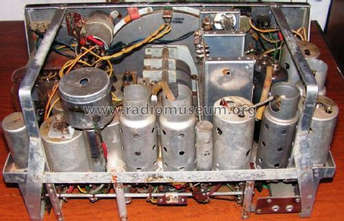
The R1155 is a single super with one HF stage and oscillator/mixer, a total of three tuned circuits, and two IF stages. With detector, BFO and AF stages there is a total of 6 valves plus a magic eye as tuning indicator. There are facilities for direction finding and homing and the D/F part has 3 valves. The set covers 75 to 1500 kHz LF/MF in two bands and 3 to 18.5 MHz HF in three bands. Bandwidth is 5 kHz @-6 dB and the sensitivity is better than 10 uV on all bands.
Although rather simple the receiver has a remarkably good performance for short and medium wave world radio listening.
My Receiver
I had an R1155 in the end of the 1950s and used it for DX-ing. I eventually sold it when I got married and had children. Now I am retired and I recently bought another R1155 which I have restored to its original state and again I use it for broadcast station DX-ing. The receiver was nearly untouched and after adding the DF valves it is like it came from the factory, probably in 1943. It is an R1155 modified to the A model by retrofitting the IF filter traps. The serial number is 32343.
Further info on my home page http://goto.glocalnet.net/bosradio
Attachments
- My R1155 with accessories (115 KB)
- R1155 chassis (108 KB)
- R1155 block installation (137 KB)
- R1155 block diagram (71 KB)
Bo Samuelsson, 22.Dec.06