6D315 Ch= 5657
Zenith Radio Corp.; Chicago, IL
- Country
- United States of America (USA)
- Manufacturer / Brand
- Zenith Radio Corp.; Chicago, IL
- Year
- 1938
- Category
- Broadcast Receiver - or past WW2 Tuner
- Radiomuseum.org ID
- 67719
-
- alternative name: Chicago Radio Lab

Beitman


By courtesy of William Kendrick, USA

Click on the schematic thumbnail to request the schematic as a free document.
- Number of Tubes
- 5
- Number of Transistors
- Semiconductors
- 100-70
- Main principle
- Superheterodyne (common); ZF/IF 455 kHz
- Wave bands
- Broadcast only (MW).
- Power type and voltage
- AC/DC-set
- Loudspeaker
- Electro Magnetic Dynamic LS (moving-coil with field excitation coil)
- Material
- Plastics (no bakelite or catalin)
- from Radiomuseum.org
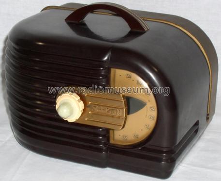
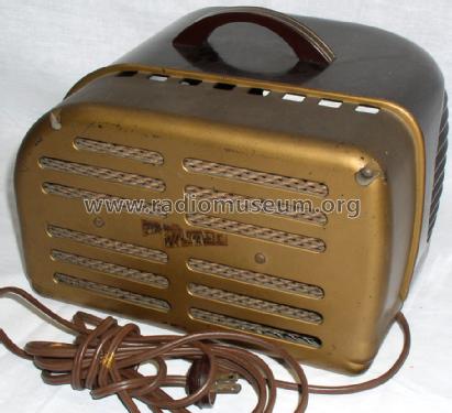
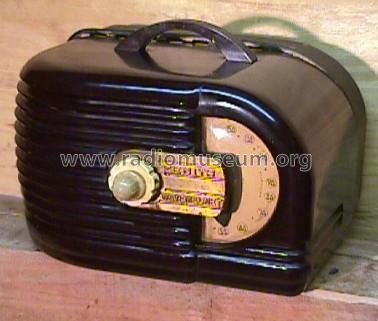
- Model: 6D315 Ch= 5657 - Zenith Radio Corp.; Chicago,
- Shape
- Tablemodel, with any shape - general.
- Dimensions (WHD)
- 10.8 x 7.9 x 9.3 inch / 274 x 201 x 236 mm
- Notes
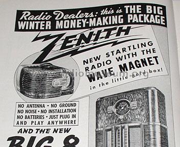
- Zeniths first Wavemagnet radio; Ballast tube.
- External source of data
- Ernst Erb
- Source of data
- The Radio Collector's Directory and Price Guide 1921 - 1965
- Circuit diagram reference
- Rider's Perpetual, Volume 10 = 1939 and before
- Mentioned in
- Collector's Guide to Antique Radios 4. Edition
- Literature/Schematics (1)
- Zenith Radio The Glory Years 1936-1945
- Other Models
-
Here you find 4517 models, 4109 with images and 3652 with schematics for wireless sets etc. In French: TSF for Télégraphie sans fil.
All listed radios etc. from Zenith Radio Corp.; Chicago, IL
Forum contributions about this model: Zenith Radio Corp.;: 6D315 Ch= 5657
Threads: 1 | Posts: 5
I am trying to restore a Zenith 6D315, chassis 5657. The problem is that MY radio does NOT MATCH the schematics available on-line or in Riders Manuals! My chassis is definitely marked 5657 on the original Zenith paper serial number tag attached to the inside rear chassis. Some of the differences are:
- The wavemagnet antanna on my radio is NOT SHIELDED as is the one shown in the schematic. The bottom socket where the wavemagnet shield plugs in is empty. The remaining plugs and wiring to the wavemagnet look original, including the lead to the external antenna screw. I just cannot imagine someone removing the wavemagnet shield!
- My set uses a 6K7G IF amplifier tube, and not a 6U7G. And the TUBE SOCKET is marked 6K7G!
- The 6Q7 grid resistor in my set is 15meg and not 1 meg. And bias resistors R5 and R6 are NOT INSTALLED in my set (and apparently never were - all resistors look original).
- R4 in the AVC line is 2.2meg vs. 1 meg in the schematic.
- The two wire wound resistors R9 and R10 differ from the schematic. R10 (the one that goes to ground) is marked 12 ohms and measures 12 ohms. R9 looks like it is marked 40 ohms (yellow/black/black) but measures 100 ohms - but sometimes colors fade or change with age and heat. The resistor is a Micamold type and is somewhat bulged. If it really should be a 40 ohms resistor then it needs to be replaced, but with WHAT? The schematic shows 60 and 50 ohms for R9 and R10. But R10 in my radio is original and is both marked and measures 12 ohms!
Has anyone else encountered this variation and can verify the value of resistor R9? Thanks!
Dave McClellan, 08.Dec.13