A very simple one-tube transmitter
A very simple one-tube transmitter


- only one tube


With the used 4P1L valve, the suppressor grid must be connected to the screen grid.
To thank the Author because you find the post helpful or well done.
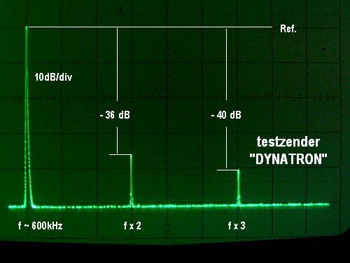
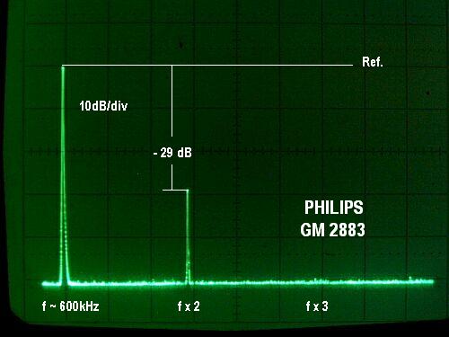
Oscillation measurements.

Hello Wolfgang,
Great to see the great response that your Dynatron has generated. We have here another great RM classic thread!
The various responses to the German version of this thread, in particular with the RV12 P2000, have stiumulated further curiosity.
It would be interesting to see some signal measurements at the center of the cathode filament, and for screen current.
The cathode output shown in one of the RV12 P2000 circuits, should affect the oscillation frequency less, but it may still affect it's amplitude. But your carefully chosen 10pF output coupling cap into a two segment 2k load should also make your frequency very stable.
It would be interesting to see what your p-p plate swing is, as compared to a plate sweep of your tube.
I found the diagonal nature of the distortion in your scope photo quite interesting. This would not be expected in a mixer, but in a modulated oscillator, this can occur if the tuned bandwidth falls below the modulating frequency.
I expect that when the Audio lowers the screen voltage, it reduces the plate voltage width of the negative resistance region and also reduces the negative slope. This effect can be seen in these tetrode configuration curves of the DF97.
When the negative slope drops, the Q of the circuit rises, as the positive and negative conductances become nearer each other. This explains the reduction in bandwidth that causes the diagonal distortion. By the way the distortion level in your Dynatron is perfectly acceptable, it just stimulates curiosity.
When the Screen voltage is following a high positive audio peak, the negative plate conductance matches the linear conductance of the tuned circuit, by letting the plate swing far enough outside the negative slope, into the positive slope, such that the "average slope" matches the resonant circuit losses. This mode is very responsive to the audio modulation because a small change in plate voltage easily changes the penetration into the positive conductance outside the negative slope reagion.
When the Screen voltage is follwoing a low negative audio peak, the negative slope region shrinks in plate voltage width in the curve family, but the negative slope also gets weaker because of reduced cathode current. This causes the slow response and the diagonal distortion.
This brings to mind, that the response might be improved by applying enough audio modulation in reverse audio phase, to the control grid, to keep the cathode current constant, when the screen voltage drops. If the control grid proportion of signal is correct, the negative slope would stay fixed over the modulation range, and only the plate voltage width of the negative region would move in response to the audio. This response should be quite linear.
Sorry, if I got a bit carried away with this analysis, but you put up such an interesting circuit!
Regards,
-Joe
p. s.: No need to rush with measurements.
To thank the Author because you find the post helpful or well done.
Summertime ?
Kind regards, Wolfgang
To thank the Author because you find the post helpful or well done.
Improvement
As already mentioned in 2009, the Dynatron-TX worked to my satisfaction. However, the AC heater supply for the 4p1l caused a more or less residual hum modulation.
I experienced this phenomenon in the past during investigations replacing the RES164 by the Russian 4p1l. Due to differences in the filament geometry at the production process, this cannot be compensated by the 100 Ohm potentiometer at all!

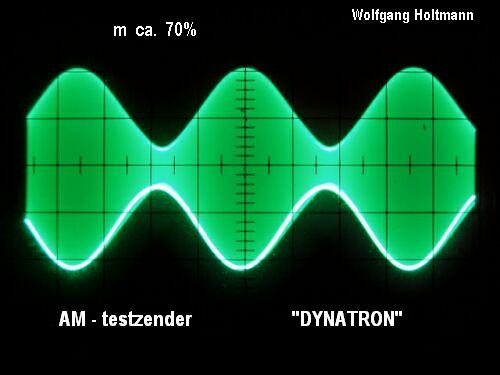
This drawback can be circumvented by heating the tube with DC-voltage. Further experiments showed clearly, reducing the filament voltage as low as only 2.5 volts instead of the nominal 4 volts, gaining the advantage of a modulation depth up to 80% with relatively low distortion. Please observe also the adapted voltages at the screen grid and plate. Those values are critical because of the limited working range of the Dynatron.
Note: In order to get a clear indication of the envelope at the output, it is of importance to suppress any residual LF. I did this by connecting an RF-choke (appr. 1mH) in parallel to the vertical input of the scope.
Furthermore I made some measurements on the unwanted frequency modulation of the carrier wave. This item has to be taken in account seriously with all AM single stage oscillators.
By observing the voltage swing at the screen grid during modulation with a sine wave, I substituted the same variation with an external DC-voltage and took the reading from the frequency counter. The result was a surprisingly low deviation of around 100Hz for 65% modulation depth and maximal 200Hz for 80%!
Not bad for this simple one-tube approach of a Home Transmitter.
To thank the Author because you find the post helpful or well done.