Converting a Russian 6e5s (6E5C) in an EM11
Converting a Russian 6e5s (6E5C) in an EM11

I do know that it would involve socket replacement, but how would one go about to place the correct wiring to the pinout as well as right resistor?
Thanks,
Omer
EE:
We post such very good articles directly to the tube. We use transcription and small letters for Russian tubes to distinguish clearly from american types. I did now the correctionsfor you.
To thank the Author because you find the post helpful or well done.

You would rather convert from the original EM11 tube, which creates the familiar cross shaped indication, to the 6E5C tube which creates only the single sector indication, as opposed to replacing the EM11 with a very good USED or NEW EM11 tube?
Herr Hans Kamann has posted a pin and resistor correlation for the EM34 to the 6E5C conversion - see thread 26125.
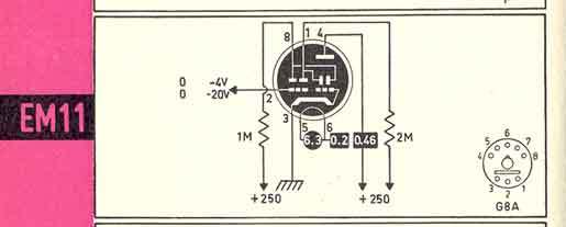
Pin basing layout for the EM11 which has the F8/G8 base, shows the following pins for the respective items within the tube:
Pin Number_____Ident.
1______________A2
2______________G2
3______________K, G1
4______________L
5______________F
6______________F
7______________Not used
8______________A1
The original 6E5 design had noticeable limitations, and the 6G5 eliminated those limitations. Presumably the 6E5C reverts to the earlier design limitations. Please excuse the digression.
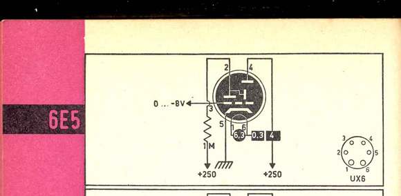
Pin layout for the modern 6E5C tube is as follows:
Pin Number_____Ident.
1______________Not used
2______________F
3______________A
4______________Not used
5______________G
6______________L
7______________F
8______________K
Continuing on (and respectfully using the format of Herr Kamann):
a. On the replacement octal base for this "EM11-6E5C conversion", solder a 1M ohm resistor between pins 6 (L, the target) and pin 3 (anode).
b. Reconnect wire from old EM11 pin 2 onto pin 5 (G), and solder connection.
c. Reconnect wire from old EM11 pin 4 onto pin 6 of 6E5C base, and solder connection.
d. Reconnect and solder filament leads F(from pins 5 and 6 of EM11 base) onto pins 2 and 7 of new octal base.
e. Reconnect and solder cathode lead K (from pin 8 of old base) to pin 8 on new octal base.
I would be most grateful if Herr Kamann or Herr Roschy, or any other member, would kindly review this old man's interpretation of conversion, and offer constructive critique.
Respectfully und
Mit Freundlichen Grussen,
Robert
To thank the Author because you find the post helpful or well done.
illustration

would be most grateful if Herr Kamann or Herr Roschy, or any other member,
would kindly review this old man's interpretation of conversion, and offer
constructive critique.
Hello Robert, for your assistance, here an "picture" to show also what is to do.
Greadings, Hans 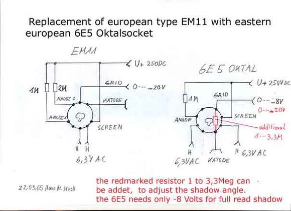
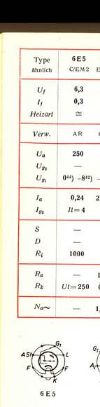
this datas are from an ex GDR Databook 1956
To thank the Author because you find the post helpful or well done.
Many thanks to my Esteemed Friend
I agree that I should have added photos. . .and I have quite a few.
However, I am still unable to use correctly the WYSIWYG editor although I have 5 Browsers. My son tells me I must "Uninstall" the incorrect Java I presently have as default.
I am sure you know in the earliest years of the 6E5, the limitations of the -8 volts for full closure. When Sylvania developed the 6G5 in 1937, the grid had been changed so that the plate current cutoff would occur at about -22volts insteaed of the -8 volts for the 6E5 tube. As a result, the tuning indicator became more "meaningful", and the eye would most likely rarely ever fully close.
Thank you so much for information in red. . .I was going to ask about a similar situation with an adapter that I have just completed:
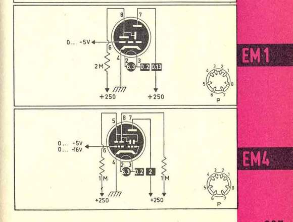
I have a European sidepin octal socket that appears to be made for earliest eye tubes EM1 and EM4 (the socket has small hole in bottom center for attachment purposes) - and there is resistor 1.0M ohms from screen to anode 1; also there was resistor 6.0M ohms from screen to anode 2.
Question - Is resistor with 6.0M ohms not typical?? . . . . .mostly I see resistors from 1.0M to 3.3M ohms as you depict in the illustration.
I will submit that item under a separate thread, and attach some supporting photos.
It also relates to a different tube pin number sequencing pattern.
Dr. Omer Suleimanagich should be able to make the conversion in a satisfactory manner.
Respectfully,
Robert
To thank the Author because you find the post helpful or well done.
More infos
Hello Robert,
i now your trouble with WYSIWYNW, i mean what you see, is not what you want!
O.K. Lets go
Is resistor with 6.0M ohms not typical?
No! for EM1, 2Meg is normal and for the EM4 two pieces of 1Meg is normal.
In some design, it can be different. The angle of shadow can be changed with this Value.
But the full variation of angle, 90 to 5°, is only posible with the recommendet values.
I have add three Figures from an Book "Muiderkring" (Netherland) where the typical dimension drawn.
for more information this diagramm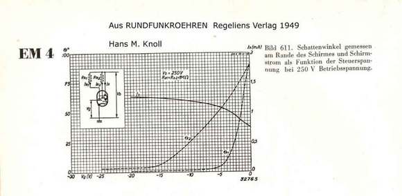
The redmarked resitors in my paper, builds an divider with the resistor in the set there is nomaly inline with the negative voltage wiring to grid No. 1.
see here: http://www.radiomuseum.org/dsp_tube.cfm?tube_pk=669
This version you can find in Tapercorders to align. the right recording level.
all right Robert, i hope you can agree!
Best regards Hans
To thank the Author because you find the post helpful or well done.
I agree completely
Yes, I agree completely - all circuits that I have seen for the eye tubes do reflect the 1M ohm or 2M ohm resistors. It is quite probable that a different tube may have been installed in that peculiar socket.
When I am testing these eye tubes I should place the required resistance across the respective pins to most accurately simulate operating conditions?
While creating the tube adapter for any of the "P" based tubes, I had to remind myself to "invert" the wire numbers from the P base to the American octal (which is same as European F8/G8 base) to properly use the Hickok tester.
Thank you so much for the clarification.
Respectfully,
Robert
To thank the Author because you find the post helpful or well done.
its fine if you agree. I think, its a good thing to assist the friends in US.
Regards Hans
To thank the Author because you find the post helpful or well done.
Converting an EM11 to a 6E5C
Thank you so kindly for the quick and excellent reply regarding this topic!
As you know, about the only cost effective replacement for these mid century beauties that we so much enjoy restoring, maintaining, and discussing, is the Soviet 6E5C magic eye tube.
This is why I feel a lot of discussion the forum should be centered around this topic of magic eye replacement.
With luck, if there is ever a shortage of the 6E5C's and a demand, you could be rest assured that some Russian vacuum tube company will start producing them again. This said, many of the other magic eye tubes are basic museum pieces, and their future resurrection at this time is plain futile!
Kind of like America's Apollo space program, with all the equipment and documentation destroyed, and just pictures and prototype museum pieces at Washington D.C.'s Smithsonian.
After recently purchasing a '52 Telefunken Andante, I'm currently clearing the ground work for its restoration.
I thank you for this information, and I hope others can benefit as well!
I see in the working schematics that experimentation is needed to see whether a 1-3,3 MEG resistors needs to be added for normal function.
Ballpark(as we say in the States) what in your estimation would need to be added to make a 6E5C functional in let's say a Telefunken radio using an EM11?
Omer
To thank the Author because you find the post helpful or well done.
what in your estimation would need to be added to make a 6E5C functional in let's say a Telefunken radio using an EM11?
I think, for this andante 52, the right value is 1,0 Megohm
This value depends in other sets from the dimension of many details of design.
I have make an calculation for andante, and my oppinion is 1.0 Megohm.
Regards Hans
To thank the Author because you find the post helpful or well done.
Converting an EM11 to a 6E5C
Thank you for your input and I hope that members can now benefit with this information.
It will be especially helpful for those that will be receiving their shipment of magic eye vacuum tubes that were recently presented to the RMorg memebers.
All the very best from Los Angeles
Omer
To thank the Author because you find the post helpful or well done.