
6Е5С6e5s

|
|
|||||||||||||||||||||||||||||||||||

 Röhren")

|
Hits: 6284 Replies: 0
6e5s (6e5s) Anpassung der 6E5C
|
|
|
Jacob Roschy
17.May.11 |
1
Magische Augen wie die EM4 oder EM34 benötigen -16 V zur Vollaussteuerung, während die 6E5C nur -8 V benötigt. Ersetzt man eine EM4 oder EM34 durch eine 6E5C, so ist diese schon bei mittleren Signalen voll ausgesteuert, der Bereich von mittleren bis starken Signalen ist dann nicht mehr zu unterscheiden. Mittels eines Spannungteilers kann die Anzeige der 6E5C richtig angepasst werden. Normalerweise befindet sich in einem Radio schon ein RC- Filter, das verhindern soll, dass die Anzeige im Takt der Modulation flattert. Dies ist in Bild 1 Teil A, durch R1 und C1 dargestellt. Durch hinzufügen eines weiteren Widerstands R2 nach Masse in Bild 1- B, entsteht ein Spannungteiler, der die Steuerspannung des Gitters der 6E5C herabsetzt. Dieser Widerstand R2 muss so gewählt werden, dass nur noch bei starken Signalen Vollaussteuerung erreicht wird. Der Wert von R2 ist abhängig von der vorhandenen Steuerspannung und dem Wert von R1. Er muss daher durch Versuch ermittelt werden. Man kann zunächst ein Trimmpoti von 3...5 MΩ einbauen, das man auf die gewünschte Anzeige abgleicht. Der ermittelte Wert wird dann durch einen Festwiderstand ersetzt.
|


|
Hits: 3848 Replies: 7
6Е5С (6Е5С) - Precoce deterioramento
|
|
|
Gabriele Seccia
06.Oct.15 |
1
Buongiorno , avrei una domanda alla quale nn rieso a dare risposta : quale potrebbe essere la causa di un precoce diminuzione di luminosita' su un occhio magico ? saluti Gabriele |
|
Biagio Laureti
07.Oct.15 |
2
Ciao Gabriele, Saluti Biagio |
|
Gabriele Seccia
07.Oct.15 |
3
Grazie Biagio molto chiaro. Saluti Gabriele. |
|
Biagio Laureti
07.Oct.15 |
4
In merito all'occhio magico, è disponibile sul sito digilander un interessante articolo su l'indicatore di sintonia. |
|
Gabriele Seccia
08.Oct.15 |
5
Grazie vado a documentarmi . Saluti Gabriele |
|
Gabriele Seccia
11.Oct.15 |
6
Ciao Biagio ho visionato l'articolo da te citato in precedenza , molto interessante . Ma controllando le tensioni sul mio 6E5C e verificandole con la sua scheda tecnica , ho notato una qualche diversita che a me pare sospetta ( premesso che la sua luminosita iniziale la vedo piu fioca rispetto a quando l'ho montato ) , non vorrei che fosse pervenuto un qualche altro problema altrove nel ricevitore , comunque le tensioni da me verificate sono : P8 = 0 Volt P5 = - 0,5 Volt ( contro i - 4,0 Volt ) P3 = 30 Volt ( mi sembrano un po pochi con la resistenza da 1 Mhom nuova ) P6 = 210 Volt Saluti Gabriele |
|
Biagio Laureti
16.Oct.15 |
7
Ciao Gabriele, in merito al tuo problema posso aggiungere:
A conclusione di quanto esaminato, ipotizzo l'opportunità di sostiure l'6EC5 a seguito dell'esaurimento del fosforo, comunque, dato che l'esperienza suggerisce sempre nuove soluzioni, è possibile che a qualche nostro associato vengano in mente altre idee. |
|
Gabriele Seccia
16.Oct.15 |
8
Bene Biagio , grazie della completa spiegazione tecnica , il mio dubbio era solo se qualche tensione da me rilevata non fosse a norma , ma a quanto pare e' tutto in regola , diciamo che a conti fatti il problema e' inerente ad un deterioramento del fosforo ,provvedero alla sostituzione . Grazie Saluti Gabriele |
|
Hits: 3810 Replies: 0
6e5s (6e5s) Heathkit IT-17 emissions tester settings
|
|
|
Paul E. Pinyot † 2013
02.May.12 |
1
Tube tester setting derived from cross referencing pin diagrams and experimentation: Tube Type Fil Plate Top (T) Bottom (B) 6E5C 2 6.3 30 CE GH Normal Short (Bold) not idetified 6E5C 4 6.3 0 F CEGH OPEN when Test Switch Activated 6E5C 4 6.3 0 CF ECH Closed when Test Switch Activated. I do not know what Bottom (B) toggle switches normally show short when toggled. These are normally indicated by BOLD lettering. These will possibly work with IT-21, IT-3117 and TC-3 Have Fun, Paul |
|
Hits: 5974 Replies: 0
6e5s (6e5s) Matching the 6E5C
|
|
|
Jacob Roschy
17.May.11 |
1
Magic eyes like the EM4 or the EM34 requires -16 V control voltage for full output, while the 6E5C requires only -8 V. If an EM4 or an EM34 is replaced by a 6E5C, even signals of medium strength producing full scale indication, while the range between medium and strong signals no longer can be recognized. By using a voltage divider, the 6E5C display can be adjusted correctly. Usually a RC filter is already located in a radio set, which is designed to prevent the fluttering of the display in the rhythm of the modulation. This is shown in Figure 1 A, constituted by R1 and C1. By adding a further resistor R2 to ground, as shown in Figure 1 - B, a voltage divider is formed, which reduces the control voltage to the 6E5C control grid. This resistor R2 must be chosen in the manner, that only at strong signals full scale will be achieved. The value of R2 depends on the available control voltage and on the value of R1. Therefore it must be determined by trial. You can first install a trimmer of 3 .. 5 meg ohms which has to be adjusted to the desired display. The determined value will then be replaced by a fixed resistor.
If this method is not successful, probably caused by a too low value of R1, one may install a trimming potentiometer R2 of 2 ... 5 meg ohms, as shown in Figure 2 – B, which is to adjust as desired. Following the trimmpot R2 a further capacitor C2 of 10 .. 100 nF is required to suppress ripple effects. |
|
Hits: 3737 Replies: 0
6e5s (6e5s)
|
|
|
Sinisa Trlin
20.Feb.09 |
1
Hello Hickok 6000 settings for testing 6e5s are: 6e5s 6,3 HS-5608-0 100 100 A ------ eye open 6e5s 6,3 HS-5638-0 100 100 A ------ eye closed Variation of shunt (english) control can regulate shadow angle by few percent. Hickok 539B/C settings are: 6e5s 6,3 HS-5608-0 0,0 -- P4 G ------- eye open 6e5s 6,3 HS-5638-0 0,0 -- P4 G ------- eye closed Bias and shunt variation have no affect and should be set to 0,0.
Regards Sinisa |
|
Hits: 3429 Replies: 0
6e5s (6e5s)
|
|
|
Sinisa Trlin
19.Feb.09 |
1
Hello Hickok 533A settings for testing this tube are: 6e5s 6,3 JR-5607-0 -- -- P4 ------ Eye open 6e5s 6,3 JR-5637-0 -- -- P4 ------ Eye closed this setings would work on all early models up to 600 model. 539A, KS-15560 also. This setting will NOT work on 539B/C, 6000, 752 ect. Regards Sinisa |
|
Hits: 3393 Replies: 1
6e5s (6e5s) Prüfkarte für Funke W19
|
|
|
Klaus Pahr
11.Jan.09 |
1
Hallo zusammen, wer kann eine Prüfkarte für diese Röhre für das Funke W19 beisteuern? Vielen Dank. Viele Grüße Klaus Pahr |
|
Klaus Pahr
25.Jan.09 |
2
Hallo zusammen, Herr Karl-Heinz Kornath hat mir mangels Schreibrechten direkt eine Antwort zugesendet, die ich hier mit seinem Einverständnis allen Interessierten zur Verfügung stellen möchte:
Hallo Herr Pahr, Vielen Dank, Herr Kornath, für Ihre Erklärung. Viele Grüße Klaus Pahr
|
|
Hits: 5375 Replies: 2
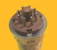
6e5s (6e5s) Pinbelegung
|
|
|
Darius Mottaghian
30.Nov.06 |
1
Bitte darum die Pinbelegung zu prüfen. Darius |
|
Wolfgang Bauer
30.Nov.06 |
2 Warum? |
|
Konrad Birkner † 12.08.2014
30.Nov.06 |
3
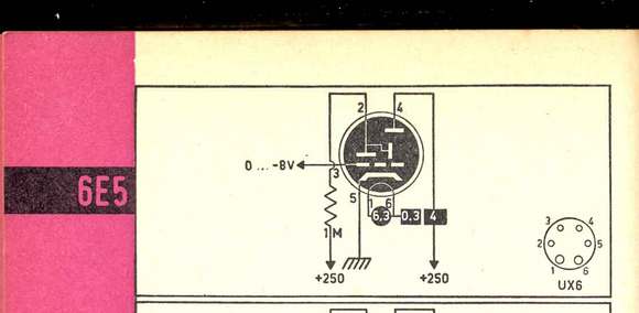
Die Pinbelegung ist doch ok. Nicht zu verwechseln mit anderen 6E5 Versionen. Da gibt es Unterschiede. Die 6E5C russischer Herkunft (hier im RMorg als 6e5s geführt, wegen der kyrillischen Buchstaben) kann die EM34 mit folgenden Einschränkungen ersetzen: - die Beschaltung ist zu ändern Zur Beschaltung Im Gerät sollte ein Warnhinweis angebracht werden: Umgebaut auf 6E5C. Dies ist kein direkter Austauschtyp für die EM34. Bei Veräusserung eines umgebauten Gerätes gebietet es der Anstand, auf die geänderte Bestückung hinzuweisen (nicht erst nach Rückfragen)! Meine Empfehlung als Kurztext in Angeboten: Von EM34 auf 6E5C umgebaut |
|
Hits: 28370 Replies: 9
Converting a Russian 6e5s (6E5C) in an EM11
|
|
|
Omer Suleimanagich
20.Mar.05 |
1
Does anyone have advice on how to convert an EM11 to a 6E5C? I do know that it would involve socket replacement, but how would one go about to place the correct wiring to the pinout as well as right resistor? Thanks, Omer EE: We post such very good articles directly to the tube. We use transcription and small letters for Russian tubes to distinguish clearly from american types. I did now the correctionsfor you. |
|
Robert Sarbell † 22.3.22
21.Mar.05 |
2
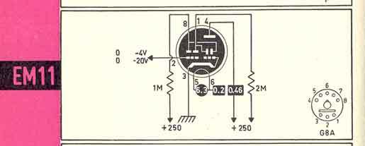
Omer, You would rather convert from the original EM11 tube, which creates the familiar cross shaped indication, to the 6E5C tube which creates only the single sector indication, as opposed to replacing the EM11 with a very good USED or NEW EM11 tube? Herr Hans Kamann has posted a pin and resistor correlation for the EM34 to the 6E5C conversion - see thread 26125. Pin basing layout for the EM11 which has the F8/G8 base, shows the following pins for the respective items within the tube: Pin Number_____Ident. 1______________A2 2______________G2 3______________K, G1 4______________L 5______________F 6______________F 7______________Not used 8______________A1 The original 6E5 design had noticeable limitations, and the 6G5 eliminated those limitations. Presumably the 6E5C reverts to the earlier design limitations. Please excuse the digression. Pin layout for the modern 6E5C tube is as follows: Pin Number_____Ident. 1______________Not used 2______________F 3______________A 4______________Not used 5______________G 6______________L 7______________F 8______________K Continuing on (and respectfully using the format of Herr Kamann): a. On the replacement octal base for this "EM11-6E5C conversion", solder a 1M ohm resistor between pins 6 (L, the target) and pin 3 (anode). b. Reconnect wire from old EM11 pin 2 onto pin 5 (G), and solder connection. c. Reconnect wire from old EM11 pin 4 onto pin 6 of 6E5C base, and solder connection. d. Reconnect and solder filament leads F(from pins 5 and 6 of EM11 base) onto pins 2 and 7 of new octal base. e. Reconnect and solder cathode lead K (from pin 8 of old base) to pin 8 on new octal base. I would be most grateful if Herr Kamann or Herr Roschy, or any other member, would kindly review this old man's interpretation of conversion, and offer constructive critique. Respectfully und Mit Freundlichen Grussen, Robert |
|
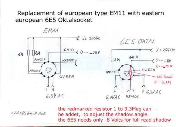
Hans M. Knoll
22.Mar.05 |
3
would be most grateful if Herr Kamann or Herr Roschy, or any other member, Hello Robert, for your assistance, here an "picture" to show also what is to do. Greadings, Hans |
|
Robert Sarbell † 22.3.22
22.Mar.05 |
4
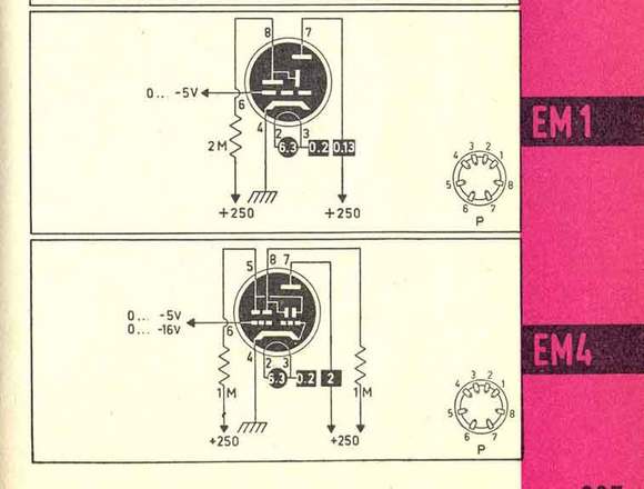
Good Afternoon Hans, I agree that I should have added photos. . .and I have quite a few. However, I am still unable to use correctly the WYSIWYG editor although I have 5 Browsers. My son tells me I must "Uninstall" the incorrect Java I presently have as default. I am sure you know in the earliest years of the 6E5, the limitations of the -8 volts for full closure. When Sylvania developed the 6G5 in 1937, the grid had been changed so that the plate current cutoff would occur at about -22volts insteaed of the -8 volts for the 6E5 tube. As a result, the tuning indicator became more "meaningful", and the eye would most likely rarely ever fully close. Thank you so much for information in red. . .I was going to ask about a similar situation with an adapter that I have just completed: I have a European sidepin octal socket that appears to be made for earliest eye tubes EM1 and EM4 (the socket has small hole in bottom center for attachment purposes) - and there is resistor 1.0M ohms from screen to anode 1; also there was resistor 6.0M ohms from screen to anode 2. Question - Is resistor with 6.0M ohms not typical?? . . . . .mostly I see resistors from 1.0M to 3.3M ohms as you depict in the illustration. I will submit that item under a separate thread, and attach some supporting photos. It also relates to a different tube pin number sequencing pattern. Dr. Omer Suleimanagich should be able to make the conversion in a satisfactory manner. Respectfully, Robert |
|
Hans M. Knoll
22.Mar.05 |
5
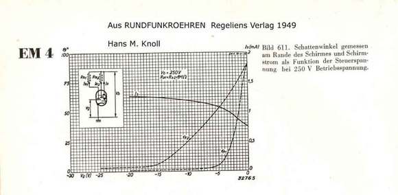
Hello Robert, O.K. Lets go I have add three Figures from an Book "Muiderkring" (Netherland) where the typical dimension drawn.
|
|
Robert Sarbell † 22.3.22
23.Mar.05 |
6
Greetings Hans, Yes, I agree completely - all circuits that I have seen for the eye tubes do reflect the 1M ohm or 2M ohm resistors. It is quite probable that a different tube may have been installed in that peculiar socket. When I am testing these eye tubes I should place the required resistance across the respective pins to most accurately simulate operating conditions? While creating the tube adapter for any of the "P" based tubes, I had to remind myself to "invert" the wire numbers from the P base to the American octal (which is same as European F8/G8 base) to properly use the Hickok tester. Thank you so much for the clarification. Respectfully, Robert |
|
Hans M. Knoll
23.Mar.05 |
7
Hello Robert, its fine if you agree. I think, its a good thing to assist the friends in US. Regards Hans |
|
Omer Suleimanagich
24.Mar.05 |
8
Gentlemen! Thank you so kindly for the quick and excellent reply regarding this topic! As you know, about the only cost effective replacement for these mid century beauties that we so much enjoy restoring, maintaining, and discussing, is the Soviet 6E5C magic eye tube. This is why I feel a lot of discussion the forum should be centered around this topic of magic eye replacement. With luck, if there is ever a shortage of the 6E5C's and a demand, you could be rest assured that some Russian vacuum tube company will start producing them again. This said, many of the other magic eye tubes are basic museum pieces, and their future resurrection at this time is plain futile! Kind of like America's Apollo space program, with all the equipment and documentation destroyed, and just pictures and prototype museum pieces at Washington D.C.'s Smithsonian. After recently purchasing a '52 Telefunken Andante, I'm currently clearing the ground work for its restoration. I thank you for this information, and I hope others can benefit as well! I see in the working schematics that experimentation is needed to see whether a 1-3,3 MEG resistors needs to be added for normal function. Ballpark(as we say in the States) what in your estimation would need to be added to make a 6E5C functional in let's say a Telefunken radio using an EM11? Omer |
|
Hans M. Knoll
24.Mar.05 |
9
Hello Omer, what in your estimation would need to be added to make a 6E5C functional in let's say a Telefunken radio using an EM11? I think, for this andante 52, the right value is 1,0 Megohm This value depends in other sets from the dimension of many details of design. I have make an calculation for andante, and my oppinion is 1.0 Megohm. Regards Hans |
|
Omer Suleimanagich
25.Mar.05 |
10
Again, Thank you for your input and I hope that members can now benefit with this information. It will be especially helpful for those that will be receiving their shipment of magic eye vacuum tubes that were recently presented to the RMorg memebers. All the very best from Los Angeles Omer |
End of forum contributions about this tube
| Data Compliance | More Information |