How the german tuning indicators works?
How the german tuning indicators works?

Especially in the Set Koerting "Noblese" Type 22322
http://www.radiomuseum.org/dsp_modell.cfm?model_id=54720
Modern Tuning Indicators from Type EM84 , EM80 and so on, have include two independent electronic Systems. One part is the Amplifier, the other the Indicator -section.
The amplifier is a Triode.
Regular the AGC (automatic gain control) from the Radio-Frequency part, is an negative Voltage depends from Signal- strength of receiving Signal, or in case Tape- recorder, the value of recording Signal.
In all cases that is an negative DC- Voltage.
This voltage is connected to the grid of the Triode, via an R/C -Combination (lowpass), to remove the AC what's superimpose on DC Signal in both cases (radio und Tape).
This Signal control's the Triode and on the Working resistor on Anode circuit, performed by an Resistor from 100Kohm's to 1 Meg ohm, the Anode Voltage. This Voltage changes from low (without signal) to high (with Signal).
In normal cases the Anode of the Triode is direct connected to the Indicator part.

This Part have the Target ( leuchtschirm) an grid to distribute the electrons homodyne on Screen or Target, and a electrode called "Steg" [S] or Ray control electrode.
These electrode is direct connected with the Anode of Triode. When the Voltage on grid of the triode (AGC) goes up and down, the Anode Voltage and the Ray controlling Element goes also up and down and changed the Shadow angle on Screen on Target. This is the normal situation.
Its also possible, to make the variation of the Ray controlling system Voltage extern, not from build in Triode.
For example, they can controlled from the Screen -grid ( g2 Schirmgitter) Voltage of the IF Amplifier. e.g. Koertng Noblesse 22322.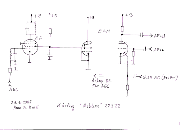
This screengrid -voltage moves equal, up and down, in the same manner like the Triode-anode, with the AGC Voltage of the Receiver.
In this Sample, Koerting Radio 22322, whe have this Variation. The Triode part of EAM 86 , is only used as Audio Preamplifier.
It is possible, that the low Anode current in this cases gives a good Performance, but Test on Tube-tester with higher current say "bad" .
That's my long explanation .
The Diode in this Koerting is used to generate an negative Voltage from the 6.3 Volt AC Heather Voltage, allow to make a delayed AGC Voltage for better Signal to Noise Ratio.
Hans M. Knoll
To thank the Author because you find the post helpful or well done.
Precise dB measurements with eye tubes.

Dear Hans, thank you for taking the time to explain eye tube operation.
I had not seen the clever use of the EAM86, with the direct deflection plate drive from the IF screen grid. I imagine that the resistance drive of the screen affects the AGC action, with a more remote cut-off.
I have been interested in the logarithmic deflection response of eye tubes.
The best tubes, with the widest range around 30dB are the EM84 and similar tubes. The earlier round eye tubes, like the 6U5 only have about a 15dB range.
This logarithmic response makes the eye tubes Ideal to measure audio signal envelope amplitudes. Every 3dB increase in negative voltage at the input of the EM84 control grid causes about 1mm of deflection. This 3dB change could be from -1V to -1.41V or from -10V to -14.1V, or a similar percentage change from a few hundred mV to the negative cutoff voltage of the EM84 around -25V.
Best regards,
-Joe
EE 27 July 2009: link was destroing format. Link deleted. We should also not get a link grave through the years ...
To thank the Author because you find the post helpful or well done.
Alternative path
An alternative way to find the AudioXpress article about eye tubes is to use a seach engine with these keywords:
"Precise dB measurements with eye tubes"
Regards,
-Joe
p.s.:The 1MB file size of the article falls outside the maximum size of 200k for direct attachment in the forum. The inclusion of incidental ads in the original magazine pages with the article may also be objectionable for forum posting.
To thank the Author because you find the post helpful or well done.
Images of 'Magic Eyes' and related Articles
See Related Articles
Images of magic eye types
How the "Tune-A-Lite" works
The Russian Neon/Argon Bargraph IN-13 (there is a less sensitive IN-9)
and History of Tuning Indicators
Here is an overview of Vintage Electronic Indicator technology (not just "Magic Eyes" or "Tuning Indicators")
To thank the Author because you find the post helpful or well done.