History of Tuning Indicators: meters, graphs, Magic Eye, LED
History of Tuning Indicators: meters, graphs, Magic Eye, LED

The history of Tuning Indicators is nearly as old as radio itself. We are not beginning with the sounders, galvanometers etc. to show a line currant and signal in telegraphy which have existed well over 100 years. We begin with the indicating tools and methods for wireless reception - not transmitters.
Today we mostly remember the Magic Eye which arrived 1935. It conquered the market well before the Second World War and was dominating for decades. Together with the rise of solid state technique the Magic Eye and tubes faded away. The Magic Eye was replaced by solid state technique like LEDs, LCD etc.
We forget that there were a few decades of Radio and Broadcasting before the Magic Eye was born. What was before the Magic Eye? It will be followed with: What are the reasons and grounds for the Magic Eye? When was it invented? How was it refined and adopted to new situations?
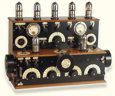
Separate Voltmeters and Milliamp-meters on a Ducretet "7-Tube-Piano-Type"
Radio from 1923/24 and its follower RM7.
The model shows 22 devices for handling it ...
No measurement possible for signal strength.
See also Zenith Multiceiver MC-3 from 1921. Here you find an example of a Remler radio (Superhet 1924/25) with a voltmeter for battery conditions to help adjust the rheostat. This Scott Radio (1926) uses a voltmeter which can be switched for A battery (filament, Volts) or B battery. See also Mende Superhet EZ123 from 1925.
Summary of this history:
Already in the first decade of the 20th Century Radio Amateurs exchanged wireless reception reports, partly read from a signal strength meter. Meters on TRF receivers were used as an aid for tuning rather than as a measurement and these were usually in the plate circuit of the detector – see Marconi of about 1920. Signal sources were anode current from one or more RF tubes, screen grid current (amateur RSGB handbook 2nd ed 1940) or rectified current from 2nd detector.
For the beginning of the broadcasting time, say from 1922 onwards one can find a few expensive radios with meters - only for measuring the batteries. Some circuit improvements were needed first for measuring in principle the way we do now. That has first to do with AVC (Automatic Volume Control - later referred to as AGC Automatic Gain Control).
Most listeners forget that their set is constantly receiving signals that have a variable strength ratio which reaches 500,000 times to one (without counting the modulation). You receive a stable reception (no fading) and can forget the volume knob when switching between very weak and very strong stations. The optical or visual tuning aids were leading also to "silent" tuning (QAVC, RCA pat. 9.12.1928).
For several reasons the Superheterodyne receivers called even more for good tuning indicators which also should well integrate in a living room. The meters were luxury items, followed by shadow meters, neon indicators etc. until 1935 (Europe 1936) the Magic Eye began to wipe out all this methods. But all those other means had to be found and refined. They show us interesting principles etc.
The Magic Eye was the cure - but it had to be adapted to several new demands like double action for weak and very strong stations, FM, stereo, change of style etc. Remember the big difference in strength ... Not included are the different places and aerials. We don't forget some of the many other fields in which the Magic Eye did a good job. The most known to us are different measuring instruments for radio repair, signal level for tape recorders etc.
Very roughly one might say that since the Solid State Technique, there was a change to also solid state tuning indicators - and to PLL, scanners etc. Those "instruments" would also be an interesting story to tell because there were quite different approaches. Topics are Nixie Tubes (is also a Neon tube!), banks of light-emitting diodes etc. Now we look at the start of all this:
A: Radio Amateurs
B: Early signal strength meters (before AVC)
C: AVC Automatic Volume Control
D: The first variable-mu tubes for AVC
1: Signal strength meters (AVC)
2: Shadow tuning meters
3: Shadowgraphs (reactor principle)
4: Dimming pilot lamp
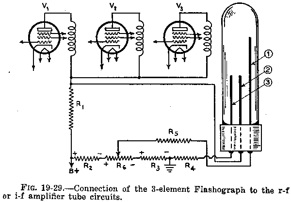
5: Flash-O-Graph (FADA)
6: Saturable core reactors and bulbs
7: Neon indicators
8: Magic Eyes
9: Post Magic Eyes
A: Radio Amateurs
Just as a reminder: in 1898 there were already several Radio Amateurs corresponding with wireless stations by Morse Code. Soon after the availability of de Forest Audions some few began also transmitting speech and music. De Forest made experimental broadcasting in 1907 from his laboratory in New York City and in 1908 from the Eiffel Tower in Paris etc. (Fessenden started 1906 with an alternator).
But already for morse transmitting, code signal strength and other conditions played an important factor. Here started the use of a reception signal strength meter. Wikipedia: "An 'S meter' (signal strength meter) is an indicator often provided on communications receivers, such as amateur radio receivers or shortwave broadcast receivers. The scale markings are derived from a subjective system of reporting signal strength from S1 to S9 as part of the RST code. The term S unit can be used to refer to the amount of signal strength required to move an S meter indication from one marking to the next."
RST code (Readability = understanding, Strength, tone quality)
To ensure that everybody had the same conditions for the exchange of quality reports the Short Wave Radio Amateurs set clear rules and those were wide-spread by 1912 (Titanic). Wikipedia:
"The RST code is used by amateur radio operators, shortwave listeners, and other radio hobbyists to exchange information about the quality of a radio signal being received. The code is a three digit number, with one digit each for conveying an assessment of the signal's readability, strength, and tone. The code was developed in the early 20th century and was in wide-spread use by 1912. Most S meters are not calibrated and in practice can only provide a relative measure of signal strength based on the receiver's AGC voltage. Some S meters are calibrated to read S9 for an input of -73 dBm but do not provide the correct 6 dB per S unit correspondence."
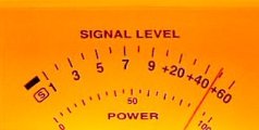
Wikipedia picture: S-Meter of a Ten-Tec Orion amateur radio transceiver.
+60 = 60 dBµ = or 1.0 mV/m
S 9 = -73 dBm. This is a level of 50 microvolts at the receiver's antenna input assuming the input impedance of the receiver is 50 ohms.
S meters for AM show an "S" 1- to 9 (with 6 decibels (dB) difference for each number) and above the decibels which exceed the 9. Example S2 = -115 dBm or 0.40 microvolts in 50 ohms on HF, S9 = receiver input power of -73 dBm = 50 microvolts in 50 ohms (VHF bands -93 dBm or 5 microvolts in 50 ohms).
B: Early signal strength meters (before AVC)
Galvanometers or Milliammeters (Moving Iron or Moving Coil Meters) are used.
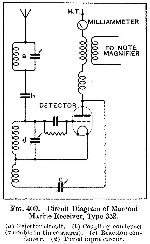
See the Marconi Type 352 Marine Receiver. Note magnifier = AF amplifier. See also the Western Electric Receiver 10A.
C: AVC Automatic Volume Control
The most important factor which allowed easy signal strength indication at all is AVC. From the 1940's it was called AGC (Automatic Gain Control). One can read in "Development of the art of radio receiving from the early 1920's to the present" by W. O. Swinyard (Page 125): "... on 2 January 1926, Wheeler invented his diode AVC and linear diode-detector circuit. This circuit was first incorporated in the Philco Model 95 receiver which he designed at Hazeltine laboratory and which was announced about September 1929." But: The first patents I found are:
Wheeler: Original application filed July 7, 1927, serial no. 203,879, and in Great Britain July 3, 1928. Divided and this application filed November 10, 1930, serial no 494,558. patented Sep. 27, 1932 as 1,879,861. "Volume Control". But see also Espenschied and Bowen (1921 Bell). Against drift Clarence W. Hansell filed Nov. 1, 1927 a patent "Automatic Tuning" for RCA, patented May 9th 1933 as no. 1,907,965. For automatic tuning, John E. Gardner of Chicago, assignor to Grigsby-Grunow, filed a patent August 23, 1926 with title "Radio Receiving System", which was published as patent 1,897,252 Fab. 14, 1933. Alan Douglas told me about it, because it covers also other issues which are of interest here, like signal-seeking. There are co-pending applications, serial number 123,528 and 129,717 mentioned, also for 1926.
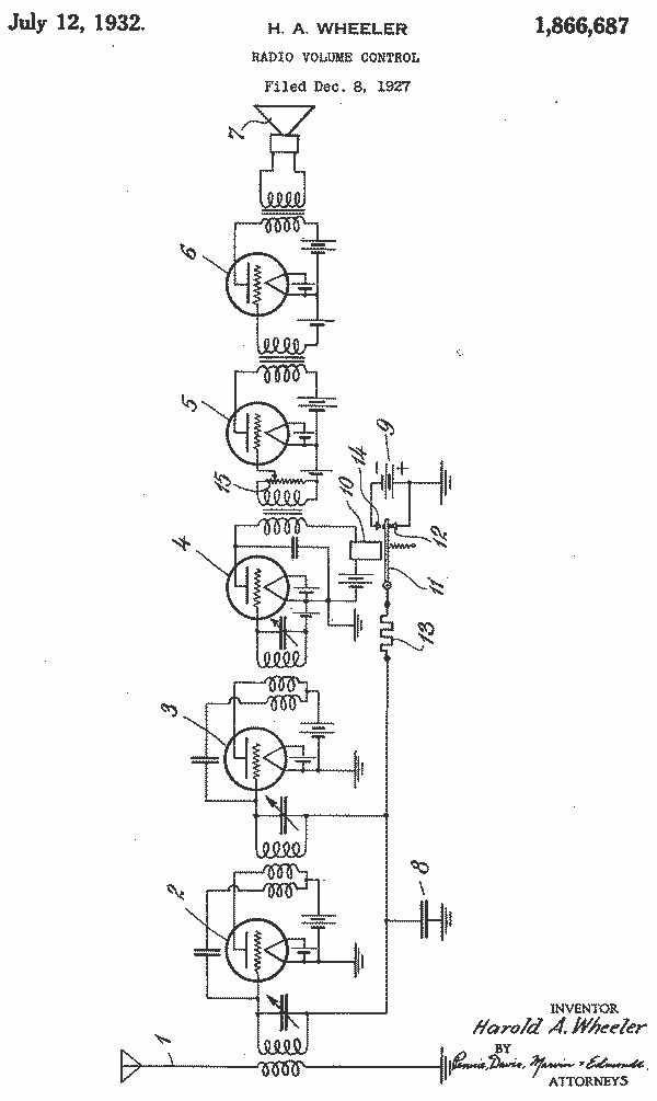
Harold A. Wheeler Filed Dec. 8, 1927 "Radio Volume Control" serial no. 238,488, patented July 12, 1932 as 1,866,687.
Object: To provide simple and effective means for securing and maintaining substantially constant output volume - that is to say, substantially uniform signal loudness irrespective of variations in the strength of incoming signals. (fading, different stations with different field strength). Applying variable grid-potential bias on the HF amplifier tube ... Condenser no. 8 = 1 uF or more ... between grid and filament of one or more of the RF amplifier tubes. The function of the condenser 8 is to provide an automatically variable potential bias (from battery 9) on the grids of the first two tubes (2, 3). The purpose is to impress upon these grids an increasingly negative bias in response of increasingly strong incoming signals and, vice versa a decreasingly negative bias. Relays (10, 11) with contact 12 and 14 and resistance 13 are used as time basis for a smooth operation.
At least Wheeler's later design included a milliammeter as a tuning indicator. He and others worked on such patents on AVC like:
Otto H. Schade filed Aug. 9, 1929 "Automatic Volume Control" serial no. 384,612 patented June 27, 1933 as 1,916,129 assignor to Atwater Kent Manufacturing Company of Philadelphia: Silva application, serial Nr. 361,910, filed May 10, 1929.
Walter van B. Roberts, assignor to RCA filed March 30, 1929 serial no. 351,410, patented June 13, 1933 as 1,913,959: Historically, the first receiver to show self-governing characteristics, with reference to its amplification volume, was the resistance coupled radio frequency amplifier employing high resistance values of grid leak. He brings in a "magnetron amplifier circuit" which has a battery ...
D: The first variable-mu tubes for AVC
In 1929 begins the problem of cross modulation in the USA caused by strong signals of similar frequency and nonlinearities in the first stage. Stuart Ballantyne and Harold A. Snow (Boonton Research Corp.) found a first answer with the tube 551 later called 51 (Arcturus, Majestic, Raytheon May 1931) with "gradual cut-off" (vari-mu, gradual cut-off, GE experimented in 1919 in vain). Probably first publ. IRE paper December 1930. Soon after the 551 remote cut-off tube, RCA came with the same tube called UY235 (235 later 35 - and later joined as 35/51. In Japan called UY-235). An article, June 1931 in "National Radio News" shows how necessary they were. In short: Trade show in Chicago in 1931 73% pentode and 94.5% variable-mu tubes. In the same year Philips brought the E445 and Cossor the 220VSG. This was a "super control feature for AVC" as Silver-Marshall stated for model 726. The problem: a high negative voltage is necessary and therefore a special AVC tube is involved for the RCA solution. See General Motors model 220 S-10B (1931). Philco used the Wheeler invention (released Oct. 1929) with its model 95 Screen Grid (1929) where a UY-227 triode works as a combination: detector and AVC diode.

The trick was done with variable spacing of the grid wire spiral. The differential spacing has to be done very smoothly. The second generation of variable-mu tubes had a closer grid spacing to the cathode to get a lower grid voltage requirement so that it was easy to use the direct way via a diode rectifier without the need for amplification of the bias signal.
Different appereance and function for tuning indicators
There were first moving pointers (meters) then at about the same time projected meter pointers, change of intensity or color for bulbs, pilot lamp or Neon as well as pattern indicators like linear neons and graphs, later Magic Eyes and solid state indicators. Here you find only some of the better known systems and methods:
1: Signal strength meters
Used were simple meters - or in the case of some manufacturers, optically clever solutions to suit the decor of the cabinet. Lets start with a nice one:

Zenith starts 1932 with a meter - impressive. Such meters were inverted here for having best signal with the needle at the right when the instrument gets small current only: the higher the input signal the lower the plate current of the AVC tubes. In other words: the meter deflection is inverted to the RF signal strength.

Zenith 103 Ultra from 1932 (perhaps 1931/32) shows a Signal Strength Meter (and Push Button Tuning for 9 stations!).

The detail of the meter is seen on this Zenith model 92 from 1931/32 with the writing: "Tune for greatest swing to right" You can just see the needle in the right corner for a strong station. Photo by courtesy of Mason B. Cohen.
Signal Strength Meters in Europe
A normal approach is to have a meter, shadow indicator with needle or Neon indicator within the path of the Anode current for the 2nd IF Filter like we find it for Weltsuper 660WL from Telefunken Austria in 1933, for Zerdik Weltmeister RU743 (1934) or Selectric U5 RU561 (1935).
See a nice physical location of a meter within the scale (right) like for Philips Denmark Octode Super 626HU-17 from ca. 1935.
By the way: Germany started in 1933 to introduce tuning indicators: Meters, shadow meters and Neon indicators. Examples for simple meters are Mende for model 1934G, 1934W, which are "single range superhets" (Einbereichsuper). exporversion is Super Select 1934 - and model Ultraselektiv.
2: Shadow tuning meter
We use this term for a "Shadow Tuning Indicator" or Shadow Indicator with a normal instrument behind a translucent screen, showing only a shadow from the needle. Below you will find the other principle with a rotating shutter or vane with a coil around it. Both use the light from a rear mounted lamp.
Shadow Indicators in Europe
Example Germany: Tuning Indicators were introduced in 1933: I could not find one before that date for the bigger 32 manuafcturers but in 1933 at once about a dozen had them in the top models. They are either just meters, shadow indicators or neon indicators. AVC / AVG was introduced in 1932.

Left: 1933 Stassfurter Imperial 53.
Right: 1934 Philips 640A .
Both show the shadow indicator above the scale.
3: Shadowgraph
To drive this, the anode circuit of the IF amplifier or detector was used - for instance the 6A7.
The principle:
A vane or shutter produces a variable shadow from a rear mounted lamp onto a translucent screen. The shadow is in the middle and varies varies by its size both sides of the shadow equally depending on signal strength.

Problems: The wax on the windings melted causing the vane to stick. Sometimes a double peak was apparent due to a bent vane. 10mA meters were used initially and later 8mA models.

Solutions of two big competitors:
Early version Philco Shadowgraph
The early version from 1932 has a screw base (46) lamp, the late version a bayonet base (44) lamp, both for 6.3 volts, 250 mA (Vol 9 Rider's).
Philco Model 15X (and 15DX) from 1932 with 4 gang variable condenser (band filter entry), a tuning indicator meter and push-pull output. Detector rectifier, triode 37, is used as a diode (anode on ground). The AVC negative voltage is fed over R40 and R28 to bias the grid of 1st IF and via R17 and coil 19 the 1st detector and through R9 the RF stage bias.

.jpg)
There is a rectangular cutout area above the scale that allows light to pass through the disc, surrounding the control vane.
Late Version Philco Shadowgraph
An example is the Philco model 37-630X from 1936 with its versions with a shadowgraph in series with the 1st IF circuit and 1st detector anode. See YouTube for a film of Shadowgraph in action.

Look only at the bar on top of the (moving) scale
to see the Shadowgraph working.
This simple solution which acts similar as a later Magic Eye in form of a bar was used by Philco on many models during 1932 through 1937/38. As Philco 200X from 1934 shows, the tuning aid could also have its own dedicated control tube (here a tube type 37). Until 1937 more than 150 models had this device. You find this Shadowgraph also on Philco Model 012 Output Meter.
Zenith Shadowgraph
1933 Zenith works also with a Shadowgraph for instance Zenith model 610 (all chassis 2037 except for model 516).

Model 935 from 1935 = right picture above
below right Model 1004 (series) season 1936/37.
OTHER Manufacturers with Shadow indicator (Shadowgraph):
Atwater Kent uses the principle for instance in models 310, 510, 711, 808A of 1933/34.
4: Dimming Pilot Lamp
Some very simple sets used also just the pilot lamp to show the condition of reception. The word is old: During the American colonial period, people kept a small flame called a "pilot" burning in order to quickly light a fire for a fireplace or for a cooking stove. So the expression is quite misleading.
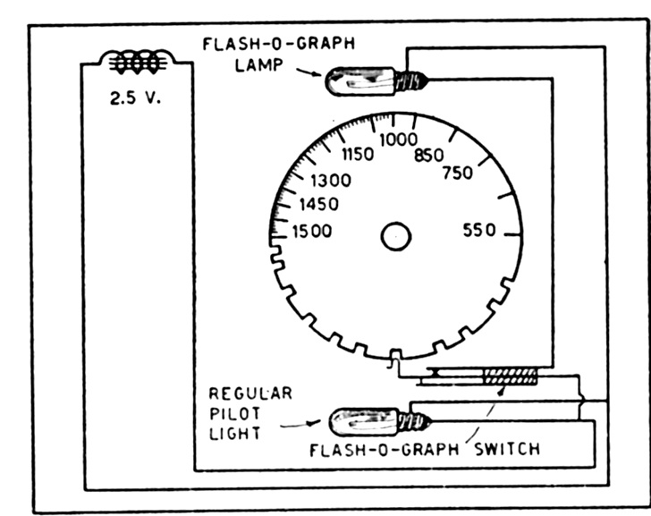
5: Flash-O-Graph FADA
This was also called Flashograph but it is a unique indication system with a pilot lamp which comes on when a station is tuned in - but just by notches which had to be made for a certain area - like New York - before installing in the models 41, 42, 44, Fada model 46 and in the model 47. The "Automatic Flash-O-Graph was the next step of FADA - which later was shortened to Flash-O-Graph only (again).
6: Saturable core reactors and bulbs
Begins with a single pilot lamp - see for instance here - which Canadian Westinghouse model 103 represents a whole family (1933). But there are quite some sophisticated systems like:
Colorama (General Electric)


Sean Barton, USA has sent me these photos. Thanks to him we see the details of the different scales coming up by switching waves. General Electric Colorama E-91 (and E-95) were the first Coloarama models.
We have included the term "Colorama" to the models with this type of tuning indicator like models E-101, E-105, E-106, E-115, E126, E-129, E-155 and the farm radios FB-72, FB-73, FB-76, FB-77. Some are simpler systems like A-205E and A-208E from later years.
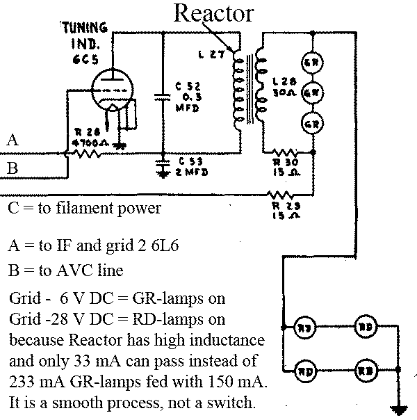
Synchro-Silent-Tuning (Grigsby-Grunow, brand Majestic)
Grigsby-Grunow started in 1932 with its "Automatic Synchro-Silent Tuning" models 300 series like Majestic 307 (addl. descr. Automatic Synchro-Silent Tuning with a reactance Resonator Indicator) and Majestic 320 etc. These 11 tube models use in principle a similar system, but just varying a tuning light by a reactor (transductor) with 3 legs of iron core. Two legs are connected in series with the pilot light, while the winding on the center leg is connected in series with the plates of the RF First Detector, and IF tubes. An electrolytic condenser (C-5) shunts the center winding for not getting any AC if there are unbalances. They call the system also "Reactance Resonance Indicator". When a station is tuned in, an automatic bias voltage is built across Resistor R-9, causing the pilot light to dim. The word "silent" comes from suppressing signals below a certain level between stations with an additional tube.
Europe
Pye in the UK uses the method 1935 for the models TP/AC and T9 Superhet. Two indicator lamps are used and in the descripton one can read: "Second valve (V2), a variable-mu H.F. pentode (Ever Ready A50N or Mullard VP4A, metallised), operates as interworking in conjunction with chokes L13, L14, L15, which have a common core. When there is no signal input to the receiver, V2 is in its most sensitive state owing to the A.V.C system, and, therefore, the anode current (D.C.) passing throught L14 is at its highest. The core is thus magnetised to a certain extent, and the inductances, and therefore the impedances, of the coils L13, L15 (in parallel) are at their lowest, with the result that the lamp (connected in series together with the mains transformer heater winding) glows brightly.
As a carrier wave is tuned in the action of the A.V.C. circuit reduces the anode current of V2 flowing through L14, and thus decreases the magentisation of the core. This, in turn, increases the impedances of L13, L15 and the brilliance of the lamp becomes less until the receiver is accurately tuned, when it glows dimly."
7: Neon Indicators
Neon indicators are an electronic approach instead of either mechanical or with conventional lamps. As with the meters or lamps one could have a simple solution by using the anode current of an IF tube. Alexander Senauke, New York, signed Dec. 16, 1929 and filed Dec. 27, 1929 his patent for a Neon lamp as tuning indicator - which was patented on Jan. 5, 1932 as no. 1,839,419. In theory the first models could have AVC based Neon tuning indicators from 1930 - but I was unable to find such models. Who knows more?
The simple 2 element neon lamp can be used - up to 4 element neon tubes:

Here a link to an article about Noise Gate QAVC Systems (see post 2) with 4 element neon tubes to act as both, a resonance indicator and a noise suppressor or noise gate. A 4 element "Gaseous Discharge Tube" was filed Aug. 23, 1933 by Senauke who got the patent in Dec. 21, 1937 as 2,103,022.

There have been quite different approaches - sometimes given a brand name:
Atwater Kent
Tonebeam used by Atwater Kent from 1931 - for instance model 96-F or in 1932 model 469-F etc.
Motorola, FADA etc.
Tun-A-Lite is the correct name for a wide spread product, but often written as Tune-A-Lite like in the linked Article. Used by Fada, Motorola etc.
FADA
The new FADA method (seee "old method" above) employing true electrical indication was named the “Automatic Flashograph” in 1931 and was introduced for the KW chassis initially on model De Luxe 48, model 49 and (1932) model 65. This was then only a two element neon indicator.
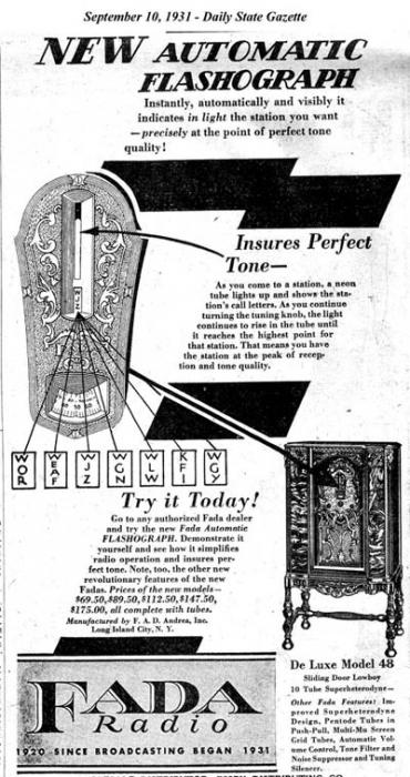
Ad above: models with KW from 1932, RA, RC and RW chassis etc.
Sparton, Sparks-Withington
Glow-Tube Viso-Glo = VG-1. Sparks-Withington uses this tube just for a very few models about 1934 like the model 136, model 83 and model 104.
Europe
Mostly it is a column with more or less illumination, but there are also other designs like the neon indicator IG-33 "Luma" (and IG-34) of AGA-Baltic in Sweden. A very interesting set is the Supra-Selector SB4345W from Körting (1935) - hear the tone example. See also Marschall 642WLK by Telefunken Austria in 1934, Erres Ky137 from 1934, Waldorp 74A from 1935 etc. use a Philips 4662 glow indicator tube with 3 elements (Schematic for guests) - up to 1941. An other late example - this time in series within the anode circuit of the 1st IF - is Radione 538U from 1937, appearing like a Magic Eye.
United Kingdom
The Tuneon is the UK's version of the Tune-A-Lite, made by G.E.C. of England and or Cossor. By the way: Button Tuneon (like the BT or CV982) are neon lamps from G.E.C. with one halo shaped electrode surrounding a center electrode centered within the halo. Striking voltage 180, Extinguishing 165, 0.5 mA current. Resistor 55 kOhm needed.
Tuneon BT from GEC - right = top view
Germany
In 1933 SABA called it "Wellen-Visierlampe" for model 521. Sachsenwerk with the cinema scale used a neon indicator (ER4093) for Eswe 346L and called it "Leuchtrohr".
8: Magic Eye
This is still a project for an other thread because this one is long enough. When we have something decent, I will link here.
9: Post Magic Eye
Also not an easy task - and reserved for a separate thread which I will link here.
My thanks go to the various members who uploaded pictures to models like Hans Amberger, Dietmar Rudolph and to Roy Johnson, UK, who gave me some pictures and helped me finding the way - especially also to improve my English wording.
The "technical" pictures "Fig. 19-xx" are from Ghirardi, "Modern Radio Servicing", 1935, the "Fig. 5-18" from Ghirardi/Johnson 1951, "Receiver Circuitry and Operation" and "289 to 291" from Ardenne, "Handbuch der Funktechnik und Ihrer Grenzgebiete", Vol. 2, 1935.
See also Joe Sousa
To thank the Author because you find the post helpful or well done.
Some additional examples of Tuning Indicators pre Magic Eye
Gradually you will find here some additional examples of tuning indicators which where used before (and sometimes also after) the arrival of the Magic Eye.
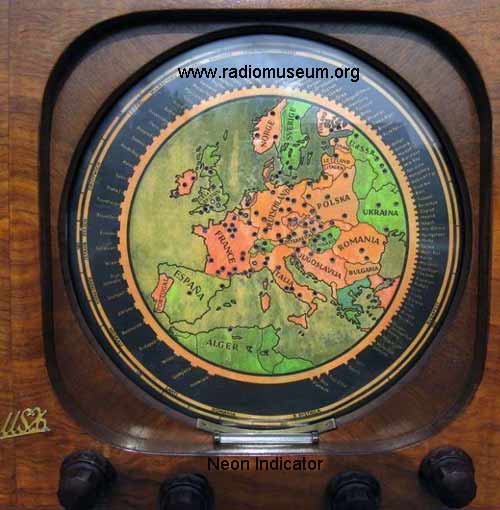
Scale of the Ingelen Geographic US26W from 1935.
This picture from Alois Steiner shows a nice scale in the shape of a map of Europe. At that time not only the Neon indicator showed a station but also one of the more than 100 light directors made from solid glass showed the physical location on the map. Unfortunately a few years later the Geographic Scales from Austria were not functioning correctly due to the change of frequencies for many braodcasting stations ... The sets are now a very interesting collector item.
Very interesting is that the idea t show a station on a map has come many years before - but the solution was quite a different one - to achieve something similar. I was not able though to find a model - but a patent only - filed March 24, 1931 by Glenn W. Carpenter for General Electric as "Geographic Station Indicator", patented Dec. 22, 1931 as 1,837,948. See the solution below.

To thank the Author because you find the post helpful or well done.
Tuning Indicators - a 1934 perspective
The attached 3 pages from Wireless World of August 10th 1934 outline the principle indicators then available and gives practical advice on their operation and application.
To thank the Author because you find the post helpful or well done.
A more complete list of manufacturers and models
I just added some Atwater Kent models with a "shadow tuning indicator" which is often called a Shadowgraph - also in connection with Atwater Kent. I don't know if Shadowgraph was a brand name or if it is just a general word for such indicators. Today for not so differentiated collectors it is just this - but I would like to know it the correct way. Any solid information on that?
Would be nice also if members send me a "Mail to the author" (see link below) or quests a contact form if they can name more companies or models which have pre magic eye tuning indicators.
To thank the Author because you find the post helpful or well done.
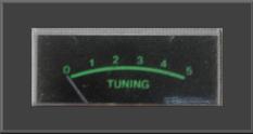
Overview and to the present
Broadcasting to the public starts in the earliest 1920s and at first if Radio sets have a tuning indicator at all it is a milliamp meter.
Then we have all kinds for strange and wonderful ideas for Tuning indicators in the mid 1920s and especially from 1930 to 1935 until the "Magic eye" or "Cat's Eye" (invented in 1934) is established as illustrated by Ernst Erb above such as the Neon Tuneon and some complex Shadowgraphs and lamp arangements as well as simpler ideas.
Sandor Selyem-Tóth has suggested some additional examples
- The Orion Reflex Super 344 with lovely shadowgraph
- The EKA shadow graph meter
- An example of a regular mA meter for tuning by EKA
Simplified Time lines for Magic Eyes
- 1935 - late 1940s: the top view, 6 pin & octal
- Mid 1950 the only miniature type DM70/DM71 (the same apart from wire length really)
- 1950s to 1960s: the Noval types, mostly side view
Here linked is overview of types of Magic Eyes and patterns.
What happens after Magic Eyes?
- Mechanical Meters (but after 1980s maybe only much on Ham gear)
- LED Bargraphs
- LCD Bargraphs
- VFD Bargraphs
- LCD bargraphs made to look like a Mechanical Meter
- All-in-one LCD and VFD displays combining "Meters", digits, text and Annunciators
After the Magic Eyes and Russian Neon Bargraphs we only have the mechanical meter as Analogue display device on a Radio of Tuning or Signal. All the Bargraph types are "on/off" technology.
Two factors led to the cessation of the wonderful glowing "Magic Eye", or "Cat's Eye" in Radio sets by the end of the 1960s:
- The change to entirely Transistor based radio sets with no valves even for Mains models. No HT for Magic Eye and too much heater current (though the DM70 and DM71 are modest).
- Availability of small cheap plastic rather than large Bakelite moving coil meters from Japan and Hong Kong
1970s to 1980s
Here are some typical models of meter in my collection removed from scrap sets of the era.
 |
Typical from a UK stereo radiogram with separate speakers. Mid 1970s |
 |
Only the raised part of the meter case is visible on the panel |
 |
Heavy blue filtered Meter behind the dark blue perspex of the cover of tuning scale on a USA stereo Tuner-Amp. Late 1970s. Only visble when rear lamps lit. |
 |
1980s from Asian make CB Radio. The red and green is translucent and backlit. Still common in 2011. |
These Meters are all to approximately the same scale.
1990s to 2011
Originally when Amateur and Professional radio got Digital readout (Nixie then LED) for frequency the driving was by discrete logic or a frequency counter IC. In later 1980s when Microprocessor controlled the synthesiser and PLL and display cheap enough for domestic radio the signal level or tuning was still an analogue meter or a separate IC driving an LED bargraph as the cheap consumer processors didn't generally have an internal analogue to digital converter.
By the late 1990s it was possible for the microprocessor to "read" the AGC line and operate a simulated meter or bargraph integrated into the same LCD (portable, car or mains) or VFD (Car or mains) panel that also displays frequency, memory channel, reception mode(s) and any other desired information.
The LCD won't displace the VFD as the VFD takes actually less power if you need bright backlight, and the VFD being a triode valve works at temperature extremes that destroy or freeze the liquid in an LCD cell. The VFD is also oddly more robust and very much less degraded by UV light with time. But for compact battery portable applications the LCD is supreme, and when no backlight is needed surpassing OLED.
The early 60s is really the end of Magic Eyes in the last AM/FM valve radios and the last tape-recorders to use them.
I looked hard at the DM70/DM71 and found almost nothing in the UK using it and few battery Radio in Germany. But many portable Tape recorders and some mains radios in Germany and France.
Then with the transistor radios they occasionally use cheap meters (More often mains Transistor sets than portables) or LED bargraphs (Sony ICF2001D maybe the best quality example, diagonal LED bargraph beside LCD). But the majority of sets don't use any tuning indicator.
Only "ham" gear continues to commonly have signal meters. The VR500 must be the smallest 100kHz to 1300MHz AM/FM/SSB radio with full LCD signal bargraph (for signal level and simple spectrograph), VFO knob and direct keyboard entry.
There are three methods used to drive bargraphs from the Radio Signal for tuning
- Integrated circuit with analogue input from perhaps AGC and compartors to drive a moving dot or filled bar. LM3914, LM3915 and LM3916 are best known. But Texas parts common too.
- Microprocessor with an on board ADC to read AGC line or similar and control either a bargraph or an entire complex LCD/VFD display panel with simulated meter or bargraph.
- A "Software Defined" (SDR) or "Digital Signal Processing" (DSP) Radio. In this case the digital samples of the signal in the internal filter are examined and either the display is controlled directly or a microcontroller used for all the knobs, buttons and displays gets the signal information by serial data.
Related Articles
- How the German Tuning indicators work
- Magic Eye Patterns
- Overview of Electronic Vintage Indicator Technology (no Meters or other Mechanical displays) which extends to numeric display of Frequency and simple Annunciators, not just Tuning Indicators.
- Neon Indicators including Tuneon list
- The Tune-A-Lite
- IN-13 Russian Bargraph for Signal Strength
- Lifetime of the Magic Eye
- Substitution of EM34
- Substitution of EM11
- Operation of the DM70 or DM71
To thank the Author because you find the post helpful or well done.
More tuning indicators

In addition to the many tuning indicators listed in the comprehensive overview given by Ernst, I would also remember two more families used in the past.
Electroluminescent quartz crystals
The electroluminescent quartz crystals, or leuchtquarz, as far as I know were used only in some German sets. I remember their use inside the Torn.Fu.f I believe: not sure of the exact model, since I owned a couple of them some 45 years ago. In these sets, the electroluminescent quartz was used in the transmitting section as a passive resonator to check the accuracy of the tuning dial just in one preset point. The neon gas inside the glass envelope gave a faint glow when the quartz was driven at its resonance. More info and even an English article illustrating its operating principle are given here. In the article Prof. Dietmar Rudolph also loaded pictures of a Loewe twin electroluminescent resonator, probably intended to calibrate even the dial span.
It would be nice to know more about the sensitivity and other applications of these devices.
CRTs
Another widely used indicator was the cathode ray tube or CRT. This was a versatile indicator, capable of giving even other details in addition to the tuning indication. Of course, due to its very high cost, its use was confined to top class sets and to military equipment.
The most known applications of CRTs were inside the mythic Marantz 10 and 10B FM tuners. In these tuners, in addition to display the IF envelope, CRT could also display the AF and, very important, it could be switched to operate as multipath indicator, giving the IF envelope on the Y axis and the detected signal on the X-axis. This function was extremely useful to orientate the antenna in the direction of minimum reflections. Other high-end FM stereo tuners offered the provision for connecting an external oscilloscope.
CRT indicators were used by military in some radar microwave receivers during WWII, as in the AN/MPG-1 or in the AN/FPG-1, but they found their use of election in receivers with built-in or external FSK and DFSK decoders. Here the CRT was used to show, as segments or dots, ‘marks’ and ‘spaces’ of a single (FSK) or of a dual (DFSK) channel teletype signal. The display allowed the optimal centering of mark and space frequencies. Countless examples of radioteletype receiving equipment using CRT can be done, from the VLF receivers used aboard submarine ships, as the AN/BRR-3 tunable down to 14KHz, to the many shortwave systems as this Elmer Communication Receiving System SR11.
To thank the Author because you find the post helpful or well done.
Early works on tuning indicators, H.W. Parker, H.M. Wagner
In its article "Tuning Indicators, A Review of the Various Visual Tuning Devices Available and Some Suggestions as to Their Use" of August 10th, 1934, "Wireless World" brings the reasons for and some of the used systems. Roy Johnson has loaded this article up after I wrote abut the same subject. Most people think that the Magic Eye of Allen Balcom Du Mont was the first idea to use a miniature cathode-ray-oscillograph. But there were several patents before. One in particular, the Micromesh Tunograph, was an interesting solution and is described in that article. Fortunately the article as such was written before Du Mont filed his patent - and proofs that other solutions were at hand.
Standard Telephones and Cables (STC) realized this Cathode-ray Indicator. It functions by causing a green spot on the fluorescent screen to vibrate at the frequency of the received carrier wave. This creates a green line on the fluorescent screen and the length of the line can be made to vary with the strength of the incoming signals. The light is caused by the strikes of the stream of electrons on the fluorescent screen. The stream is emitted from a hot cathode, fouused and moved laterally by deflecting plates like in an ordinary CRT tube - but having only one pair of deflecting plates.
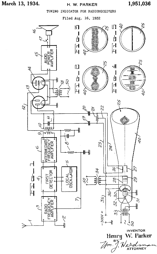
H. W. Parker filed Aug. 16, 1932 a patent for "Tuning Indicator For Radioreceivers" and received in March, 13, 1934 a patent 1,951,036 for the following device:
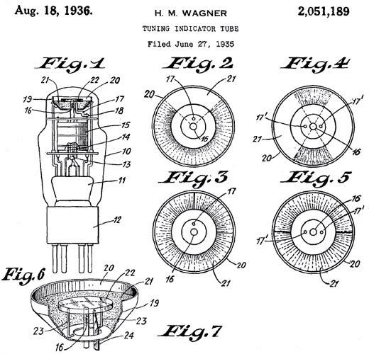
H. M. Wagner also filed his "Tuning Indicator Tube" in June 27, 1935 and received the patent already Aug. 18, 1936 number 2,051,189. That causes believe that he was the first if one looks only to the patent number or date.
Also the patent of T. J. Scofield for a "Gas Discharge Tuninbg Indicator" he filed Jan. 25, 1935 was patented earlier, June 14, 1938 as 2,120,955 (a new Viso-Glo), than Du Mont's.
There have been many patents before the Magic Eye for tuning indicators based on the CRT tube but we can clearly give the credit to Allen Balcom Du Mont for the Magic Eye which came on the market 1935. The 6E5 was registered by RCA on June 27, 1935 and used by RCA in consoles in 1935.
Allen B. Du Mont was working on "Cathode-Ray" tubes for television but we call the Magic Eyes "Electron-Ray" tubes for distinction. All are CRTs.
This is in short what I found here: "After Du Mont was an engineer for Westinghouse he became chief engineer for the De Forest Radio Company in Passaic, NJ. Presumably he worked in private since he sold the patent to the RCA in 1932. The De Forest company went into receivership in 1933 and RCA took the assets. Du Mont used his money for pioneering early oscilloscopes, television sets and TV broadcasting and prospered greatly during WW2 with defence electronics." But I did not find a patent for the Magic Eye before the one you find a picture of here below, filed Sept. 18, 1934. Still, that article is full of interesting information.
Who was Du Mont?
Allen Balcom Du Mont was born Jan. 29, 1901 in Brooklyn NY, died Nov. 15, 1965 New York NY. He joined the Westinghouse Lamp Company, Bloomfield, N.J., in 1924 as an engineer in the development laboratory. There he developed high-speed manufacturing and testing equipment for vacuum tubes. Encyclopaedia Britannica: "In 1928 Du Mont became chief engineer of the De Forest Radio Company, Passaic, N.J., where he became interested in the patents and equipment of Charles F. Jenkins, who had established an experimental television station in the early 1920s. Working from Jenkins’ patents, Du Mont set up a simultaneous picture and sound broadcast in 1930 and concluded that electromechanical systems were inadequate for practical television and that a purely electronic system was needed.
Du Mont set up a company in 1931 that later was known as Allen B. Du Mont Laboratories, Inc. He improved cathode-ray tubes and developed the modern oscilloscope, widely used in the laboratory for the measurement and study of wave forms.
In 1937 Du Mont began manufacturing the first commercial television receivers, which were based upon his improved cathode-ray tube. His company also established experimental television transmission facilities and marketed the first postwar television receivers."
His work for Magic Eyes is not mentioned.
What did Du Mont patent?
Du Mont received 419 patents, some dealing with Cathode Ray Tubes like 2,087,280; 2,098,231; 2,162,009, 2,163,256 (filed Sep. 18, 1934 see picture); 2,186,635; 2,225,099; 2,269,115 etc.
His first patent was:
Aug. 21, 1925 serial no. 51,561 for "Mount for Radiotubes", patented July 9, 1929 as 1,719,968. Third patent: Feb. 4, 1926 serial no. 86,077 a "Sound operated Circuit controller", patented Feb. 9, 1932 as 1,844,117: "...Provides a means whereby a radio set may be rendered operative or inoperative from a remote point by the creation of a given sound, as by the proper impact or clapping of the hands, thus making it possible, if desirable, to terminate the broadcasting while seated at a distant point. ..."
For tubes followed: Nov. 1928 serial no. 321,846 for improvements in radio tubes, patented Feb. 21, 1933 as 1,898,351. Or: Filed Oct. 7, 1932 "Cathode ray instrument for measuring electrical quantities", patented May 29, 1934 as 1,960,333.
The first patent for the Magic Eye:
Allen B. Du Mont, Upper Montclair, NJ, assignor to Allen B. Du Mont Laboratories Inc. filed Sept. 18, 1934 Serial no. 744,498, patented June 20, 1939 as 2,163,256.

Part of the patent text: "A cathode ray tube having beam producing means comprising a concentrating cylinder, an insulating cylinder having two holes there-through, a spacer connecting said insulating cylinder with said concentrating cylinder, a tungsten wire filament threaded through the holes in said insulating cylinder, a molybdenum wire secured to said tungsten filament, and an ocyde coating on the tip of said molybdenum wire. 2nd: A cathode ray tube having a fluorescent screen, means for producing a plurality of beams comrising a plurality of concentrating cylinders ..."
To thank the Author because you find the post helpful or well done.
Inventor of the Magic Eye Tube

Greetings fellow enthusiasts, and thank you for your excellent threads regarding tuning indicators. This topic is very near and dear to me.
I have much respect for Allen B. DuMont. He was an intelligent inventor and a major contributor to the development of television, but I don't give him exclusive credit for the invention of the magic eye tube. I believe that both DuMont and Herbert M. Wagner should share the credit for this invention. My rationale is as follows:
I give DuMont full credit for the novel idea of using a cathode ray tube for a tuning indicator. In his patent filed May 28th of 1932 entitled "CATHODE RAY DEVICE", he states starting at line 22: "It is contemplated that the invention will find wide use in connection with the indication of the tuned or resonant condition of radio receiving sets...". In the diagram in this patent, he also shows his tube as being controlled by the AVC voltage of the receiver. The device he designed, however, did not have the appearance of the magic eye tube that we are used to seeing, and was nothing more than an oscilloscope tube with a single axis. An illuminated spot would move in one direction or the other depending upon the voltage applied.
Nevertheless, RCA needed a license for this patent in order to use any cathode ray device as a tuning indicator. I'm not sure what year it was, but RCA president David Sarnoff purchased the rights from Allen DuMont. Between May of 1934 to June of 1935, various engineers working for RCA filed patents for at least five various cathode ray tuning indicator designs. One particular design by Herbert M. Wagner illustrated in patent 2051189 became the magic eye tube that we have come to know and love. Wagner's design was and still is attractive. In 1935, it was innovative, inexpensive, and very much marketable as cutting edge technology.
The origin of the term "Magic Eye" is another reason I do not give DuMont full credit for this device. I have been unable to find exactly when the phrase was first used, however, no tuning indicator was documented as a magic eye tube until after the 6E5 was introduced. The earliest document I have found using the term Magic Eye is the 1936 RCA advertising brochure where it is enthusiastically and extensively used.
Though currently have no proof (documentation), I believe that the design by Herbert M. Wagner (which resembles an anotomic eye) provoked the term magic eye.
I have intentions of some day visiting the Soda House at the Hagley Museum to look through the archives of the David Sarnoff Library to find out if information exists regarding these developments.
With Best Regards,
Howard
To thank the Author because you find the post helpful or well done.
Lesa Shadow Tuning Indicator from Italy
Our member Roberto Guidorzi is restoring a Magnadyne Radio model SV13, made in Italy (Torino).
He saw this article and has sent to me some very nice pictures and his toxt to publish here. Thank you, Roberto, I would not be able to write that nicely and precise:
"The design of the Lesa shadow tuning indicator is very simple but also very effective from a mechanical point of view (no springs, no currents in moving circuits).
Looking at the picture in attach we see that it contains a cylindrical magnetic circuit with an air gap surrounded by a fixed magnet (that can be rotated by means of an external small lever). Inside the cylinder we find the optical shutter constituted by a magnetic metal flapper connected to the cylinder by two pivots. No springs at all; the (very stable) equilibrium position of the flapper is determined only by the magnetic field inside the cylinder and by rotating the magnet around the cylinder we can change the inclination of the shutter to change, if desired, its rest position to compensate the zero-signal current through the coil.
The lower part of the magnetic cylinder is surrounded by a fixed coil with a resistance of approximately 2940 ohms that is inserted in the plate circuit of the I.F. amplifier tube. This field generated by this coil acts in an unsymmetrical way on the flapper so that the deflection of the flapper is modified by the current through the coil. Of course the flapper/shutter is inserted on the light path generated by a small lamp and its deflection modifies the length of a shadow on the front of the indicator."
The main picture for the explanations:
![]()

Here you have the looks of it. You might find more pictures on the model page (link) when Roberto has done his surely good restoration, trying to keep everything most original, at least original looking.
To thank the Author because you find the post helpful or well done.
 Thread closed by a moderator. But replies can be made through a moderator.