invicta: If Ikea had made a radio called Vicki
invicta: If Ikea had made a radio called Vicki
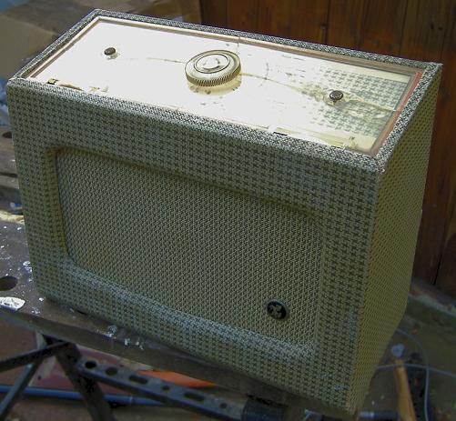
Vicki or the Invicta 26 was a set I wasn't looking for. It was in a "job" lot and I was warned that it was very poor order. I could see some of the issues... I was told the perspex top all broken and case "some" woodworm. Well, it was one of a lot working out at £5 each including postage, what had I to lose?
The original photo the seller sent. The perspex top is obviously badly cracked and handle missing.
Eventually the box of portables came (including an Ever Ready Sky Casket and Pye "Jewel Case" P114BQ). The Invicta range by 1950s is just actually a Pye marque. I was surprised that as well as being an Invicta 26 from 1955 that this Pye has an "official" name too, "Vicki".

Vicki arrives to stay with me
I had the "bright" idea of soaking the case to get the Rexine / Leatherette off in one piece and then treat the VERY extensive woodworm.
Anyway, I never leave woodwormed stuff sitting. I deal with it at once. This this the first portable I've had with Worm. So no blowtorch. I decided to soak and peel off the covering and THEN I can blow torch the bugs.
After about 15 minutes I was able to peel of most of the the cloth. The glue is very like wallpaper paste. A further 20 minutes and the bottom came off.
Of course the glue for the joints is water soluble too!

Oh.. A Kit Radio by Ikea
The parts now neatly fit in the oven. 120C in the fan oven won't hurt the wood or the oven. But the bugs die at > +30C. I'll leave that a while to make sure they are cooked through.
Woodworm
Almost all "treatments" only stop re-infestation. None of the retail fluids actually kill live woodworm grubs effectively unless the wood is completely soaked for quite a long period. Unhatched eggs are likely killed as are possibly recently hatched grubs.
You can kill the woodworm by:
- Removing oxygen
- Poison gas!
- Heat greater than 30C
- Cold below -21C
- Drying wood below 11% moisture content
Known killing options are:
- Nitrogen or poison gas for several days in a warmed sealed environment
- Blowtorch on both surfaces, especially inside. Good if the varnish is very badly cracked or scraped.
- Soak in Paraffin. No doubt this drives out the oxygen and moisture? Probably other things like household heating oil, diesel, petrol, white spirit will work. Don't combine with Blowtorch!
- Bake in an oven. With good Fan oven it's likely that 100C to 120C is fine. length of time depends on thickness of wood. Only suitable for bare wood.
- A powerful freezer < 21C, several cycles, each a day or so
I use oven (and/or Blow torch on both sides of wood till lightly "toasted"). Then soak in Ronseal Total Wood Preservative or the equivalent Cuprinol. They will kill and prevent fungus and bacterial infections.
Borax solution is allegedly as good or better than Ronseal, Cuprinol or Rentokill treatments to prevent re-infestation. The commercial preservative fluids are quite flammable. Only apply AFTER cooking!
Keep treated cabinet indoors in a warm dry location where it can be seen regularly for about 5 years as from egg to flight hole is 3 to 5 years. If there are only old black holes looking really old there may not be any infestation (but you won't know for 3 to 5 years). If there are any fresh holes, especially with dust then beetles have hatched, probably mated and died. The adults don't eat and die in a few days. Infestation ONLY is from an adult beetle laying fertile eggs. These are laid in cracks, existing (now empty) flight holes or bare wood. So after treatment the filling of all holes and varnish all seams and barewood is helpful in reducing or blocking new attacks.
The Chassis
It's a PCB. Loads of Hunts brown brittle caps. Test the C22 aka "That Cap" the Anode of pre-amp (DAF96) to grid of output (DL96). High leakage. This could wear filament badly and burnout transformer so that you lose both...

C22 must have no measurable leakage.
ALL the hunts look like shorts on the Leakage tester
-

The two screws on perspex panel should be removed and then two screws to case.
The DF96 is dead. No filament.No surpise, it died and saved the transformer, more common with DL96 than the x2 higher filament current DL91, DL92 and DL94
The Wavechange switch goes round and round. It's been forced and the contacts are all bent and one end stop bent
-

Detail of switch beside DK96 and L.O. Coil
Some poking with pliers and screwdriver and it "seems" right.
Power... some motorboating... the electrolytic across HT is supposed to be 8uF and looks sick. Reads less than 2uF. Remember the o/p tube bias is a resistor in series with HT- so the decoupling on the bench PSU is no use. Replaced with a 16uF 350V part that's half the size.
Now dead.
We get a "buzz" touching top end of volume control, but only if the DAF96 is wiggled first. Clean all the sockets. They have corroded.
Still largely dead but howls at HF end of LW. Try Sig Gem. One IF has been twiddled. The MW & LW does respond to generator so just very deaf. Test replaced DF96 and original DK96 on borrowed VCM163. Both are OK.
A wire is broken at terminal of MW coil at Ferrite. Still poor. Check the 560pf & 470pF (C11 & C12) even though they are both Silver Mica.
-
 Viewed 369 times")
- RF / Mixer / Oscillator (Pentagrid Converter DK96)
They are OK. Check Alignment. C3 has no effect to Peak LW at HF end. Suspect switch.
Poke switch and howl stops. Able to tune RTE1 LW! So lever up spring, twist past contacts, bend all the the contacts (again) and clean centre arcs. Howl now gone and MW stations & R4LW working.
L3 is LF end of MW.
C1 is Osc padding to set HF end point on MW
C2 matches the RF tuning at HF end
THEN adjust only C3 on LW. (no separate Osc HF padding/tracking on LW)
C3 now peaks LW at 280kHz
Now R4 LW working and loads of MW stations (as it's after dark, none during daylight on an ordinary radio in Ireland).
Volume and quality isn't great. But could be because the speaker is loose on the bench? Next I'll test all my DL96s on the VCM163 and compare the Dx96 series with my plug in "franken" Rod Pentodes.
To thank the Author because you find the post helpful or well done.
Rebuilding the flat pack!
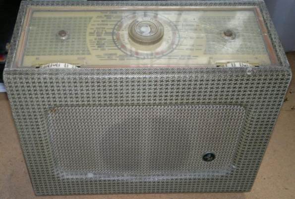
This is what the Invicta Vicki 26 (Pye) should look like

Suggestive of the later Roberts and Hacker portable/table Transistor sets covered in Leatherette.
Unlike the majority of UK Valve portables of the mid 1950s from Vidor, Marconiphone/HMV, Ferguson and Ferranti. The badge moves to speaker grill, but the hole is there under the cloth on mine!
Here are the parts treated (after baking).

Soaked for some hours in presevative after "cooking" in the oven! The dial "glass" is actually probably Acrylic / Perspex of some kind. It's gone VERY brittle and cloudy with age:
20% size scan of reconstructed "dial". It's actually the entire top of the set. So again very like later Hacker / Roberts?
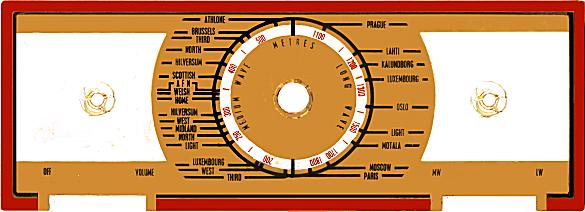
Here it is a bit cleaned up in photo editing. The "white" parts are "clear" plastic or knob cut outs. Middle hole is tuning spindle and the holes either side are mounting screws.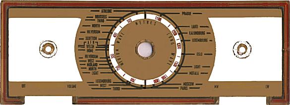
Cleaned up scan. A better high resolution version is available
Actually my scanner was getting "fooled" by the raised bezel around the edge acting like a lens.
I risked cleaning it which resulted in a better scan though some paint came off. I also switched to 600 dpi = 37Mbyte!
I could cut perspex and print all the red and black text & marking as black on laser Transparency film and then make a mask and spray beige on rear of transparency. But actually for now I have just glues the parts with "superglue"
To fill the woodworm holes I'll just use acrylic modelling paste. The various "wood fillers" I have tried are either too coarse or crumbly.
False Starts and Success
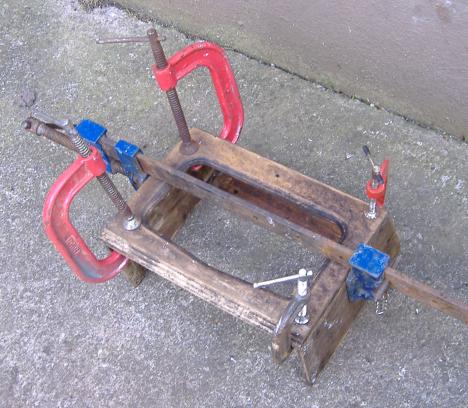
After 3 failed attempts until I realise that without more clamps, special jigs etc. that I could not re-glue all the bits of Vicki back together again in one go!
So I took it in stages.
Glue with PVA and clamp for a few hours before adding the next stage.
The base had warped so I soaked it a while in initially boiling water and left it to dry with a dead lead acid battery on it.

Then re-glued the two end pieces and clamped.
Next is gluing the base on the front and sides.

I borrowed the big clamps off Albert Lahoud.
Next glue the top bar, setting the back on to check it hooks in and clearance is OK.

Speaker Baffle

A separate piece of wood later screw to rear of front. The plastic speaker cloth was cleaned a bit with soapy water and "oxy-action" stuff. Then the wood was sprayed with glue.
Filling the Worm Holes, cracks and damage

So called "3D" or Modelling Acrylic paint was used. This is less crumbly than most fillers, goes in holes well, cheaper than "plastic wood" and dries faster than filler or "plastic wood"
Sanding it a bit

Recovering with "Rexine" or similar.
.
The stuff carefully "peeled off" after soaking leading to the original unexpected complete disintegration of the cabinet isn't perfect, but above average for this kind of set. I prefer the "plain leather effect" versions which are still readily purchased. This pattern is common and called "hound's tooth".
But finance and the fact the original isn't too bad, I re-used it. I soaked it for 15min to soften the glue again and make it easy to work. I applied and spread PVA to the wood as recommended by the "leatherette" cloth makers today. The PVA allows easy repositioning.
So when the glue has dried well it will be simple to re-fit baffle, speaker, dial on chassis and chassis. A handle needs to be fabricated.
To thank the Author because you find the post helpful or well done.
Final Result
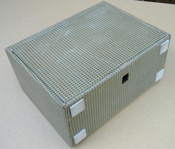
Here is the re-assembled Vicki:
I think I want to make a new perspex radio dial. The broken one is "superglued" together.

I need to make or get a little disc for centre of tuning knob. For now I have used a silver paint pen.
One side isn't quite square.
There is a problem with the battery holder space. With the soaking, dissassembly, treatments, reassembly, soaking, dissassembly, reassembly etc the space is a bit too small. I'll have to pull off the inner two batons. Yet you can see the from the back that the side panel spacing is if anything a little wider at bottom!

There is also developed a bad connection somewhere on the chassis. Intermittent.
The knobs
The two knobs are identical with a pair of red "0" like 00 about 1/2 or maybe 2/3rds around. There is only one way to assemble the knobs on the shaft to make the 00 embossed red coloured symbol either be "off" for the off/on/volume or be at "MW" or "LW" side of aperture when operated.
It's an amazing small ferrite rod for 1955.
I've used Rod Pentodes as the DF96 was dead filament on arrival. I did test and repair with the "real" tubes. But I need them for other sets They are about x5 to x10 more expensive than Rod Pentodes and much older NOS.
2 x 1j24b for the DK96 (22mA to 24mA vs 25mA, slightly better performance)
1 x 1j24b for the DF96 (11mA to 12mA vs 25mA, similar performance)
1 x 1j24b + 1N60 for the DAF96 (11mA to 12mA vs 25mA, about x4 gain in ideal circuit, similar performance with DAF96 screen grid and Anode resistors)
1 x 1j29b (with both filaments) for the DL96. (52mA to 56mA vs 50mA, about 50% more gain and twice power rating)
The Radio isn't modified at all. B7G plug adaptors are made. Slight re-alignment of IFTs is needed as valve / diode capacitances are very different
The pattern on mine is a printed simulation of "Houndstooth check" (aka "Dogstooth check") a classic quite clever effect that is inherent to to the weave of the real cloth. You can probably still get suits (Man and Lady types), but it would have been especially popular in the 1950s

Next
- Find intermittent fault on chassis (could be corroded/dodgy valve socket)
- Make new handle
- Move the two batons that retain batteries and make retention straps
- Make new dial
- Add four new feet
Photos of feet, retention straps and handle from an authentic model would be good.
Intermittent loss of signal and performance
Dodgy B7G sockets. I've abraded them with diamond cutter rod on Dremel extension cable and tweezed the socket halves. So working. But I ordered 8 x PCB sockets from Germany. These have come and are not exactly the same but should fit. The reliability is a lot better after the abrasion.
Russian Rod Pentodes vs Philips Dx96 tubes
I don't actually have a set of valves for this set. I have been using valves from other sets to test it.
I tested the 1j29b on the VCM163 on the B7G adaptor and gain with both filaments is nearly twice a DL96! With DL96 the HT current is about 8.8mA and with the both filaments a little higher with the 1j29b (about 8.9mA). I disconnected one filament on the 1j29b and gain dropped to about same as DL96 and HT current is now 7.5mA. I goes up louder than you'd want (The 1j29b can do 1W @ 150MHz on both filaments, so running it with one for 250mW Audio isn't a big deal!). (assuming series resistor between HT- and LT- is 470 Ohms.)
For complex reasons to do with not really being ordinary Pentodes (i.e. rods instead of three concentric helical grid wires), setting the g2 by simply a series resistor can be a bit unpredictable. With DF96 the g2 is 64V. With 1j24b as IF the g2 rose to 71V (which would NORMALLY) give higher Ia and ma/V gain. It was behaving strangely (possibly oscillating very slowly) so I put a 39K pull down resistor on g2 to 0V on the B7G/1j24b plug assembly which reduced g2 to 55V (45V is "recommended" but up to 60V is fine). With this operation is perfect exceeding DF96 performance.

Gain of 1j24b tested on an AVO VCM163
You do really need a small series resistor on each filament!
Note that unlike "real" Pentodes (single series resistor to HT, decoupled) the Russian Military sets use a pair of resistors as potential divider, decoupled. The g2 current is extremely low when Anode volts is "above the knee" (about 6V on a 1j24b!). Below the knee g2 and a behave like a current mirror. Also above the knee there is no g2 partition noise as g2 & g3 are really an electrostatic lens like a pair of auxiliary anodes in an Electron gun.
The HT current is now 7.5mA instead of 8.8mA and the LT current is 74mA instead of 125mA!
- DK96 heptode is replaced by Triodised Pentode as osc and Pentode using g2 as L.O. mixer port (see graph above to see why this works) driven direct from Triodised Pentode L.O. Plugs into DK96 socket. Lower L.O. Radiation, lower noise, more gain. Osc not pulled by strong stations. Previously I experimented with a single 1j24b as mixer and oscillator in the DK96 socket, but it's poor IF performance. Two 1j24b is still less filament current!
- DF96 replaced directly by 1j24b + an extra pull down resistor on G2
- DAF96 replaced by 1N60 + 1j24b (1N60 predate all Dx96 valves)
- DL96 replaced by 1j29b with only one of two filaments running.
No modification to set. Original tubes just swap. A little re-adjustment of IF, especially 1st IF for best performance. About 104mW heater/filament power and 600mW HT power!
The Feet
I have no idea what they looked like, but from mess on cloth, perhaps four rubber squares? I used not very authentic self adhesive nylon felt square pads as the cloth is badly discoloured where the old ones were.
Finally (for now)
Here are better shots

Really the same radio as the "wreck" and "flat pack"!
Feet added
The hole is for the spring clip of the rear panel

Battery "holders" fixed

Close up of 2 x 1j24b used as a DK96

Close up of 1j24b as DF96, 1j24b+ 1N60 as DAF96 and 1j29b as DL96 (one filament disconnected)
This set owes nothing as many people would have scrapped the case. A set of authentic NOS tubes is about €50 including postage. The five Rod Pentodes cost me under €15 including postage and are NOS from 1985 to 1991!
The batteries are made from cereal packets with 90gm printed inkjet glued on with Pritt. The LT is 2 x Alkaline D cell in parallel (over 26,000mAH, so at 73 to 75mA about 350 hours!). The HT can be 156 x CR2032 (6 stacks). or 10 x PP3. See this series on "Batteries Not Included" where there will be more detail.
To thank the Author because you find the post helpful or well done.