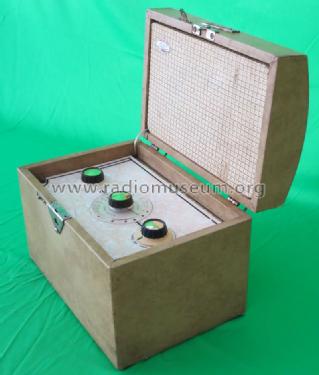
Sky Casket
Ever Ready Co. (GB) Ltd.; London
- Country
- Great Britain (UK)
- Manufacturer / Brand
- Ever Ready Co. (GB) Ltd.; London
- Year
- 1955
- Category
- Broadcast Receiver - or past WW2 Tuner
- Radiomuseum.org ID
- 71919

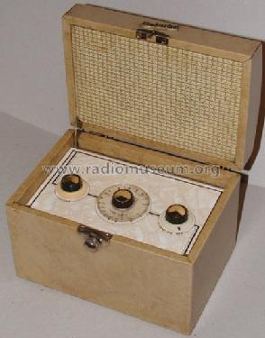
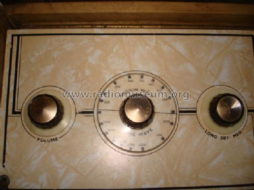
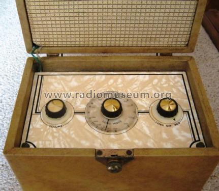
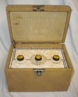
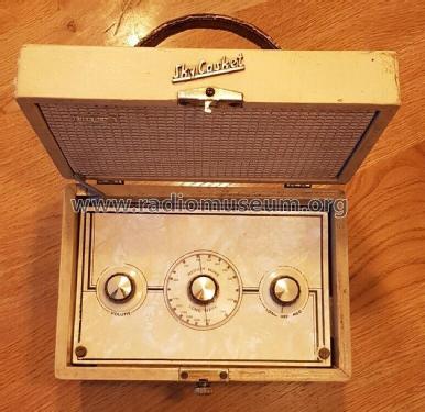
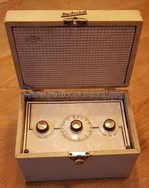
Casket open

Keith Watt RN (Rtd.)


By Courtesy Of EBAY User: ryehill_retail
By Courtesy Of EBAY User: ryehill_retail

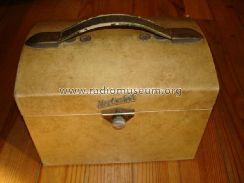
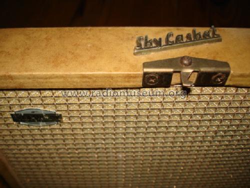
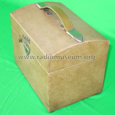
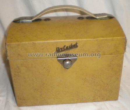
Csket closed

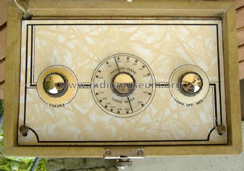
Casket open with chassis

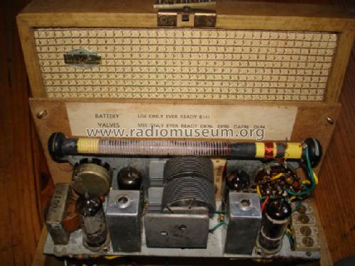
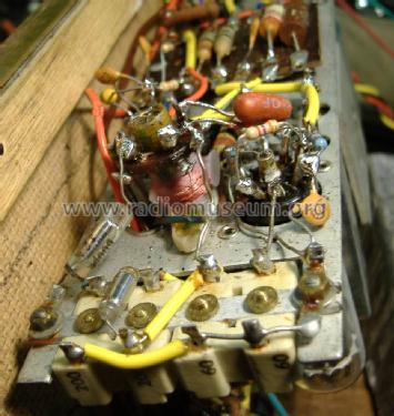
Casket chassis
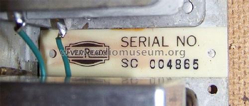
Casket label 1

Casket label 2
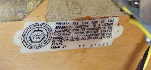
Casket label 3

Ever Ready trade mark

eBay item number:144900500993
eBay item number:144900500993
eBay item number:144900500993
Click on the schematic thumbnail to request the schematic as a free document.
- Number of Tubes
- 4
- Main principle
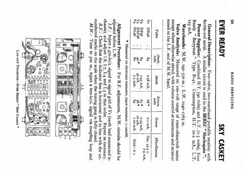
- Superheterodyne (common); ZF/IF 470 kHz; 2 AF stage(s)
- Tuned circuits
- 6 AM circuit(s)
- Wave bands
- Broadcast (MW) and Long Wave.
- Power type and voltage
- Dry Batteries / 90/1.5 Volt
- Loudspeaker
- Permanent Magnet Dynamic (PDyn) Loudspeaker (moving coil) - elliptical / Ø 4 inch = 10.2 cm
- Power out
- 0.5 W (unknown quality)
- Material
- Wooden case
- from Radiomuseum.org
- Model: Sky Casket - Ever Ready Co. GB Ltd.; London
- Shape
- Portable set > 8 inch (also usable without mains)
- Dimensions (WHD)
- 9 x 6 x 6 inch / 229 x 152 x 152 mm
- Notes
- Cost of Radio £14, 10 Shillings and 10 d. Battery type Ever Ready B141 combined HT/LT (90 volts/1.5 volts).
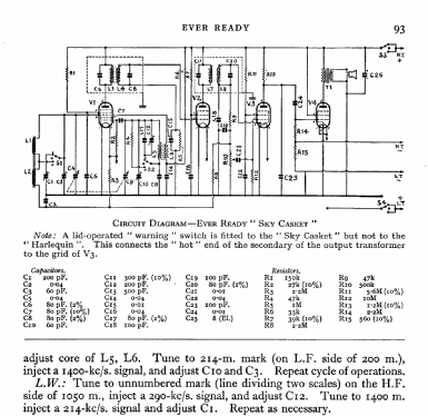
The brass contact is between "live" of the speaker/transformer secondary and the DAF96 pre-amp grid to make the radio howl if closed while on. If it cuts the audio, then the speaker wires have come off and wired back to front!
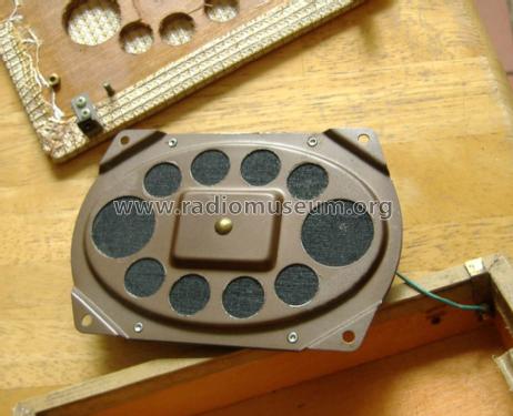
Uses a low profile inverted design of approx 4" x 6" loudspeaker (magnet is inside cone at front). Vents to improve acoustics under the carry strap / handle.
With no saving in parts, and possibly using an extra resistor, the Sky Casket has no AGC on the IF amp, DF96. The normal RF AGC on DK96 grid via RF aerial coils is still used.
- Net weight (2.2 lb = 1 kg)
- 2.340 kg / 5 lb 2.5 oz (5.154 lb)
- Price in first year of sale
- 14.00 £
- Source of data
- -- Original prospect or advert
- Author
- Model page created by Keith Watt. See "Data change" for further contributors.
- Other Models
-
Here you find 204 models, 147 with images and 92 with schematics for wireless sets etc. In French: TSF for Télégraphie sans fil.
All listed radios etc. from Ever Ready Co. (GB) Ltd.; London
Collections
The model Sky Casket is part of the collections of the following members.
Forum contributions about this model: Ever Ready Co. GB: Sky Casket
Threads: 1 | Posts: 3
I got a rather tatty one of these recently. I think maybe black with coal fire soot.
I carefully eased off the two end knobs and loosened the grub screw entirely on the tuning knob. Some shafts have a lip so the knob won't fall off if it's loose. This is the case. Some the grub screw is threaded into the shaft so has to unscrew till it falls out. I then unsoldered the two speaker wires and the feedback wire to brass contact. Mark the earthy speaker wire if the cable isn't marked.
Next I printed the under chassis view and marked all the "Hunts Modseal", the very unreliable brownish or black paper & foil capacitors from 0.01μF (10nF) to 0.04μF (40nF) on this model. Next I examined the circuit diagram to see which are critical for leakage and marked those with a * on the layout. The ones marked * will need replaced if leakage is significant due to high impedances and voltage
Here is the analysis of Hunts "modseal" paper capacitors
| Part | nF | Function | Volts | |
|---|---|---|---|---|
| C24 | 10 | grid audio coupling DL96 (o/p) from DAF96 Anode | 45 | * |
| C21 | 10 | volume control to DAF96 grid | 0 | |
| C2 | 40 | RF agc decoupling | 1.5 | |
| C22 | 40 | Pentode screen grid decoupling DAF96 | 28 | * |
| C16 | 40 | Pentode screen grid decoupling DF96 | 67 | * |
| C15 | 10 | DF96 grid leak decoupling (R5 ought to go to AGC, not 0V?) | 0 | |
| C14 | 40 | DK96 g2 supply decoupling | 30 | * |
| C5 | 40 | Heptode screen grid decoupling DK96 | 68 | * |
The DAF96 g2 feed is R11, 10M, so even slight leakage on C22 will dramatically lower the voltage.
In general
Leakage of screen grid decoupling capacitors will dramatically lower gain. No damage
C24 leakage (preamp Anode to O/P amp grid) will possibly burn out the T1 audio transformer, wear out DL96 and/or run battery flat quicker. Check voltage difference between LT- and HT-, it should be 5V to 6V.
I replaced the 10nF with * and also the 40nF with 22nF and 47nF ceramic types rated 100V that pass 350V test with no measurable leakage as the parts all tested at over 200uA leakage with 150V.
Re-connected speaker, connected up batteries and was rewarded with ... Nothing! However the speaker buzzed when the "lid close" wire touched and the signal generator heard at 470kHz. Examination of the four adjustable capacitors (Trimmers) C1, C12, C10 and C3 revealed they had been screwed absolutely tight. Common problem when an old radio stops! "Oh those pretty brass screws are loose!"
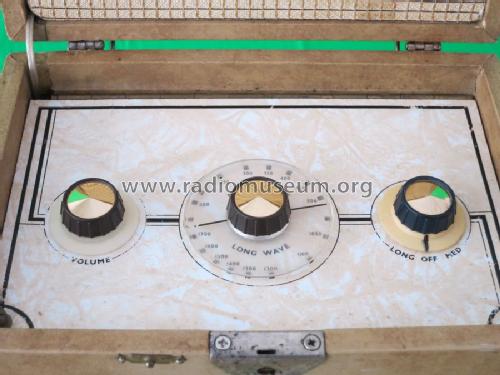
MW must always be checked before LW.
C10 is oscillator trim at 214m / 1400KHz and C3 is RF. The aerial coil and LO (local Oscillator) coil set the low frequency end of the MW band. Tuning the dial to 214m mark beside 200M and the Generator to 1400kHz I was rewarded with tone on adjusting (loosening from absolutely tight!) C10 to tune and C3 to "peak" maximum volume as I reduced generator level.
Then on LW a quick twiddle gave RTE (252kHz) close to 1200m (1190m exactly).
The problem was that though the Radio was acutally now "alive" the LF end of MW and LW was very far out (about 150kHz wrong at 600kHz) and the C10 and C12 seemed too loose (C1 and C3, the RF, not unreasonable).
I checked the IF that it "really" was on 470KHz. It was, so the phantom twiddler had left those alone. The Oscillator coil (L5 & L6) didn't look good. An experimental "poke" revealed the core was jammed, and then the radio "died".
Sniffing with Spectrum Analyser or scope on g2 (osc out) of DK96 suggested no oscillation. L6 was found to be "open circuit".
L5 was obviously the visible and larger coil wound with multi-filar fine enamel wire (the tuned circuit on g1) and the L6 the "drive" using very fine wire next to the former. But I have a plan!
Michael Watterson, 28.Jun.12