ever: Sky Casket: Repair Part1
ever: Sky Casket: Repair Part1
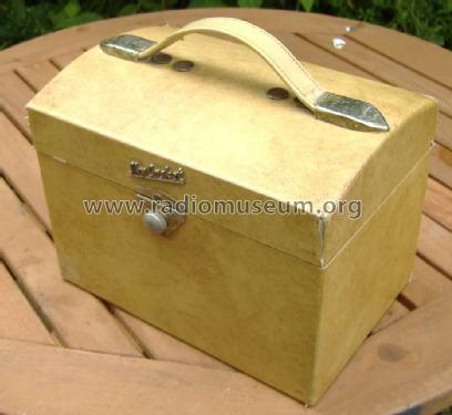
I got a rather tatty one of these recently. I think maybe black with coal fire soot.
I carefully eased off the two end knobs and loosened the grub screw entirely on the tuning knob. Some shafts have a lip so the knob won't fall off if it's loose. This is the case. Some the grub screw is threaded into the shaft so has to unscrew till it falls out. I then unsoldered the two speaker wires and the feedback wire to brass contact. Mark the earthy speaker wire if the cable isn't marked.
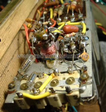
Next I printed the under chassis view and marked all the "Hunts Modseal", the very unreliable brownish or black paper & foil capacitors from 0.01μF (10nF) to 0.04μF (40nF) on this model. Next I examined the circuit diagram to see which are critical for leakage and marked those with a * on the layout. The ones marked * will need replaced if leakage is significant due to high impedances and voltage
Here is the analysis of Hunts "modseal" paper capacitors
| Part | nF | Function | Volts | |
|---|---|---|---|---|
| C24 | 10 | grid audio coupling DL96 (o/p) from DAF96 Anode | 45 | * |
| C21 | 10 | volume control to DAF96 grid | 0 | |
| C2 | 40 | RF agc decoupling | 1.5 | |
| C22 | 40 | Pentode screen grid decoupling DAF96 | 28 | * |
| C16 | 40 | Pentode screen grid decoupling DF96 | 67 | * |
| C15 | 10 | DF96 grid leak decoupling (R5 ought to go to AGC, not 0V?) | 0 | |
| C14 | 40 | DK96 g2 supply decoupling | 30 | * |
| C5 | 40 | Heptode screen grid decoupling DK96 | 68 | * |
The DAF96 g2 feed is R11, 10M, so even slight leakage on C22 will dramatically lower the voltage.
In general
Leakage of screen grid decoupling capacitors will dramatically lower gain. No damage
C24 leakage (preamp Anode to O/P amp grid) will possibly burn out the T1 audio transformer, wear out DL96 and/or run battery flat quicker. Check voltage difference between LT- and HT-, it should be 5V to 6V.
I replaced the 10nF with * and also the 40nF with 22nF and 47nF ceramic types rated 100V that pass 350V test with no measurable leakage as the parts all tested at over 200uA leakage with 150V.
Re-connected speaker, connected up batteries and was rewarded with ... Nothing! However the speaker buzzed when the "lid close" wire touched and the signal generator heard at 470kHz. Examination of the four adjustable capacitors (Trimmers) C1, C12, C10 and C3 revealed they had been screwed absolutely tight. Common problem when an old radio stops! "Oh those pretty brass screws are loose!"
MW must always be checked before LW.
C10 is oscillator trim at 214m / 1400KHz and C3 is RF. The aerial coil and LO (local Oscillator) coil set the low frequency end of the MW band. Tuning the dial to 214m mark beside 200M and the Generator to 1400kHz I was rewarded with tone on adjusting (loosening from absolutely tight!) C10 to tune and C3 to "peak" maximum volume as I reduced generator level.
Then on LW a quick twiddle gave RTE (252kHz) close to 1200m (1190m exactly).
The problem was that though the Radio was acutally now "alive" the LF end of MW and LW was very far out (about 150kHz wrong at 600kHz) and the C10 and C12 seemed too loose (C1 and C3, the RF, not unreasonable).
I checked the IF that it "really" was on 470KHz. It was, so the phantom twiddler had left those alone. The Oscillator coil (L5 & L6) didn't look good. An experimental "poke" revealed the core was jammed, and then the radio "died".
Sniffing with Spectrum Analyser or scope on g2 (osc out) of DK96 suggested no oscillation. L6 was found to be "open circuit".
L5 was obviously the visible and larger coil wound with multi-filar fine enamel wire (the tuned circuit on g1) and the L6 the "drive" using very fine wire next to the former. But I have a plan!
To thank the Author because you find the post helpful or well done.
Sky Casket: Repair Part2
How hard can it be to rewind it?
Well, if you knew the specification, not so hard. But we don't.
I carefully removed it and measured the tuned secondary (L5) to be about 85μH to 100μH (unstable). I then noted start and direction of coil and unwound it noting turns. It was obviously "wave" /"random" wound. It was about 90 turns. Under was the very fine linear wound "primary" (L6). I noted start and direction of turns. The former was cracked and coil had snapped. It was hard to exactly determine the number of turns. Maybe 30 or 40?
To experiment I used a different former and wound 35 turns, but the width was larger.... Then I random wound about 90 turns of Litz from a MW aerial taken from a scrap cheap transistor set.
This brought the radio back to life, but only on MW and only above 700KHz. Not good enough coupling of primary.
I wound another (that one will do for SW on a home brew set). with very much finer wire. This worked down to 600kHz.
So next I crunched out the old core, cleaned and glued the original former (superglue) and this time wound two layers (by simply winding on in same coil turn but back toward start at 25 T) with 50 turns total for L6. The coil was wound on a thin layer of double sided tape on the former. The coil was covered with a thin layer of double sided tape. I decided the original (very delicate multi-filar enamel wire) was too tatty and used some slightly heavier wire moving it back and forth across the L6 width while winding it to get a semi wave/random effect. At 95 Turns I measured inductance (by tinning a portion without cutting) and it was only 65μH to 70μH. So I added another 20 turns.
Wired in with no core it was just about 80kHz too high! The first larger solid core I tried mysteriously moved the frequency the wrong direction! A second attempt with hollow "hex" centre core only the length of the winding worked perfectly.
The replacement coil
Success
I then successfully followed the alignment instructions on the "Radio Servicing" sheet and the day time LW gave RTE1 and R4. Night time gave all the usual UK MW stations (Mid West of Ireland, no local MW radio).
The set doesn't perform as well on R4 LW as the BEREC Baronet (Sky Matador), which is 1958 PCB version of almost the same chassis, but has a smaller ferrite rod. But I haven't tested it's DF96 either. V2, the DF96 appears to run at full gain rather than have the negative AGC feed via R5. I replaced some resistor gone high (560 -> 670, 47K to 56K etc) but as expected little or no difference.
The experience in coil winding and understanding the effect of poor coupling or too few turns on primary will be good for the LO coils of my own design Radio Projects. While a machine is nice to "wave wind", it's not that hard to approximate it by hand.
To thank the Author because you find the post helpful or well done.
Before and After!
Before

And After
Before

And after

I used gentle applications alternately of "Cream Cleaner" (like for pots and sinks) with a sponge and soapy water. PVA glue is good to stick the "rexine" type fabric in large areas. In this case I used "Pritt" glue stick to repair joints and seams.
The speaker panel was removed from lid and speaker removed. It was then soaked fabric down in shallow solution of "oxy action" type stain removers as the fabric is glued to the plywood.
Brasso liquid and a brass fibre wire brush used to clean the rusted metal work.
To thank the Author because you find the post helpful or well done.