Questions about the 'Wunderlich' Tubes by Arcturus
Questions about the 'Wunderlich' Tubes by Arcturus

To clarify the often contradictory information of this rare kind of tubes, we (the RM) need an answer about these two items.
- The pin configuration of the “Wunderlich-A” released with an UX-5 socket with cap
Here a picture:
In the European books two different diagrams are published, sometimes even with a missing cathode! My question, which anode connection is correct?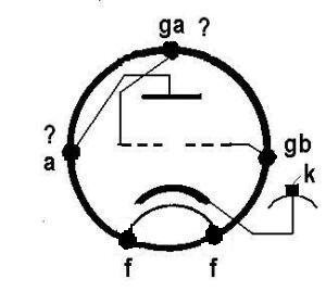
Layout 1
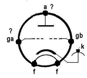
Layout 2
- The internal location of the additional grid (or plate) of the “Wunderlich-B”
Some sources talking about ....an entirely separate diode plate was added...” (J.W. Stokes)
Others see a “... separate grid near the anode” What is the truth?
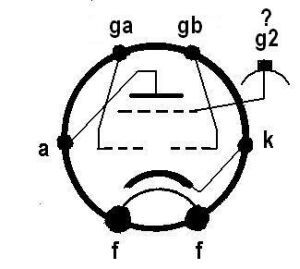
Layout 3
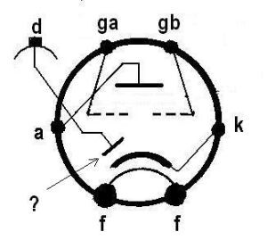
Layout 4
For more information (in the German language) click here:
A reply to my e-mail address will also be appreciated.
With thanks in advance.
Wolfgang Holtmann
To thank the Author because you find the post helpful or well done.
"Wunderlich" information
sometime ago I joined the "Tube Collector's Association" forum, so when I saw your request I asked the question of them, with two immediate replies! These are posted at present on their forum,-
probably more by now!
I think the easiest way to get to sources of the information is to join their forum by first going to - http://www.tubecollectors.org/ - there
you find a link about 2/3 down the page.
This would enable you to post questions and view all the messages between members.
Ludwell Sibley, the founder, I believe - was first to reply, with base diagrams etc. - and if you allow, I can pass onto him your email address.
Here is what they sent ----
Well, simply stated, Mr. Holtmann's Layouts 2 and 4 are correct.
Verification of Layout 2 comes from a pair of Arcturus brochures
in-file here (thank you, Jim Cross!).
Verification of Layout 4 comes from an article on the Wunderlich
B by Ed Lyon in "Radio Age" (Mid-Atlantic Antique Radio Club) for
Jan. 2000. The sainted Stokes was correct: there is indeed an
extra plate!
I had written an earlier article in "Radio Age" (May 1997) on the
Wunderlich line, but not focusing on the "B." If you'd like
physical copies of the two stories, I'll cheerfully send them.
And/or if you want to advise Mr. Holtmann to provide a postal
address, I can take care of him directly. I didn't go to the
bother of signing-up for the email group.
Incidentally, it's not widely realized that, to get Wunderlich
operation (full-wave detection plus audio gain), you don't need
the fancy tube. The Grigsby-Grunow "Majestic" Model 25 just
used a pair of humble 27 triodes!
Lud
-------------------------------------------------------------------------------
My sources are original Arcturus datasheets for the Wunderlichs plus a
1939 National Union manual. (National Union manuals are useful for
containing information on odd types they did not make).
I read the linked post. Neither given basing for the 5 pin type A is
correct. The correct US basing is diagram 5H which has:
Pin 1 - heater
Pin 2- grid
Pin 3 - anode
Pin 4 - grid
Pin 5 - heater
Cap - cathode
The basing diagram for the 6 pin Wunderlich A is US diagram 6N
Pin 1 - heater
Pin 2 - anode
Pin 3 - grid
Pin 4 - grid
Pin 5 - cathode
Pin 6 - heater
The basing diagram for the Wunderlich B is US diagram 6P, which is
given on the linked message as "layout 3"
Pin 1 - heater
Pin 2 - anode
Pin 3 - grid
Pin 4 - grid
Pin 5 - cathode
Pin 6 - heater
Cap - "anode grid"
Somewhere I have a 1930s article showing a "B", and I am pretty sure
the extra element is above the regular grid-plate structure, and that
the extra element acts as a diode.
Jim Cross - Vacuum Tubes, Inc. - phone/fax 407-481-9994
http://www.vacuumtubesinc.com
Check us out for new, used, audio, antique, and collectible types.
Vacuum Tubes, Inc.
1080 Sligh Blvd
Orlando, FL 32806-1029
Regards,
John Turrill
To thank the Author because you find the post helpful or well done.
It's amazing ...
Please pass my appreciation to the TCA Forum for the immediate replies!
Having regard to both reactions, I see a confirmation of layouts 2 and 4.
Furthermore to the so called "anode grid", in fact it acts as a diode and has nothing to do with the main anode construction. May be, that it was built as a grid around the cathode rather then a plate.
As a result of this, I will correct our internal presentation about these tube types accordingly.
Again, many thanks to all.
Wolfgang Holtmann
To thank the Author because you find the post helpful or well done.
Wunderlich B, The Experiment
Eine Übersetzung ins Deutsche ist dort im Post 11 zu finden.
From where to go?
With the help from tube collectors in the USA (Thanks to Ludwell Sibley, Tube Collectors Association), I laid my hands on an article published by the Mid-Atlantic Antique Radio Club in the January 2000 issue of RADIO AGE. Ed Lyon described the Wunderlich –B, referring to an article from Radio Engineering, March 1933.
A meaningful picture of the tubes structure (Fig.1) and a complete radio circuit using the Wunderlich-B was copied from the original drawings! Most likely from the Inventor himself, as no commercial use of this type is known. 
We can easily see the completely independent diode on top was simply added to the extended cathode. A shield was incorporated to separate the two systems.
Normally, such a diode is used for AVC purposes and this was also recommended in the Arturus Catalogue, May 1932 (Credit to Jim Cross) with the note: “Auxiliary Anode used as a Diode Rectifier; connected to top cap” In the above mentioned application, however, I discovered a different approach!

Fig.2 shows only the part, necessary for the functional description of a Wunderlich-B circuitry. This is the basic for my further investigations.
Looking at the in-circuit presentation of the Wunderlich-B, one get the wrong impression the added diode anode (sometimes confusingly called ‘anode grid’) is mounted ‘in-stream’ near the main anode.
A closer look on Fig.2
I made a new drawing (Fig.3), only focussing on the principle of the Wunderlich-B with the so called “amplified AVC” application.
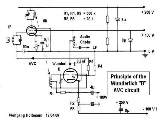
Fig.3
The clever bit is the extra negative supply voltage (-100 V) against ground !
With this trick, it is possible to get the desired negative AVC-voltage, which follows the amplitude variations of the incoming HF signal. The Wunderlich-B together with the cathode resistors R2 and R3 acts like a variable voltage divider between the +100 V and -100 V supply.
Assuming a weak signal is rectified by the grids, only a small bias voltage will develop across R1. Thus the internal resistance between cathode and anode is low. The values of R2 and R3 are chosen for a voltage, let’s say, -5 V at the cathode (K) against ground (= 0 V).
Adjacent to the cathode is the anode plate of the additional diode, connected via R4 to ground potential. A very small current will flow via R4. Seen the relationship in resistance between the diode and R4 (500k), the voltage drop across the diode is little. Therefore the AVC voltage at the diode anode (C) is almost equal to the cathode voltage. Via R5 the AVC voltage is fed to the variable-mu grids of the 58’s.
With a strong incoming signal, the voltage across R1 will be much higher forcing the current flow in the triode section of the tube to be reduced. This will also reduce the pull-up action and lower the potential at the cathode, for instance to -30 V. Again, the diode anode will follow and feed a higher negative AVC voltage via R5 to the grids of the amplifiers.
Was the extra diode superfluous?
Why not taking the AVC voltage directly from the cathode, you ask? I can think of two explanations which may make sense.
1. The additional diode can act as a threshold for a delayed AVC. In this application, the voltage at point K is set to +5V for no reception and will change to 0 V for a weak signal. In both cases the diode will not conduct. Thus the AVC at point C remains unchanged at 0V, allowing the maximum amplification of the preceding stages.
Only a stronger antenna signal can alter the voltage at K to negative values. Now the diode will conduct and the AVC voltage become negative too.
2. I see another advantage of the diode added on top. We have to go back to the original drawing (Fig.2).
The -100 V voltage is derived from the current flow through the choke in the negative leg of the power supply. If, for example, the emission of the power penthode 69 will deteriorate, the voltage drop across the choke will also be reduced.
As already pointed out, the cathode is tied to the -100 V leg via R2 and R3. For reasons mentioned above, this voltage could change to only -70 V, thus the voltage at the cathode would become positive all the time!
In case the AVC voltage is connected directly to the cathode, the grids of the 58’s will get positive too, which in turn will create an unhealthy situation! Wunderlich’s extra diode acts in this situation like a “fail save” valve, preventing such a malfunction by cutting off any positive AVC potentials.
My experimental Wunderlich-B

Fig.4
Two things had to be sorted out before getting started.
1. As necessary for all Wunderlich Detection circuitries, a good balanced HF signal is to be fed to the grids in the opposite phase.
After intensive search in my junk-boxes, I found two equal coils and another one for inductive coupling at the center of a ferrite rod. The whole is tuned to 550 kHz with an 820 pF capacitor. The frequency itself is of no importance.
2. Which tube is a practicable substitution for my investigations?
I learned, Ken-Rad and Sylvania used for their “Wunderlich” applications at that time, two separate cathodes, each with his own grid, housed in a common anode construction.
My first attempts with a 6J6 and a 6SN7 GT were not successful. I believe the anodes are mounted too close to the grids, giving just too much interaction.
Luckily, I have 6SL7 GT’s in my possession. With this type better results were obtained. To be sure about the quality of these used tubes, I made a plot of the transfer characteristics. The one with the best match of the two systems was used. The overlap is nearly perfect, as depicted in Fig.5. 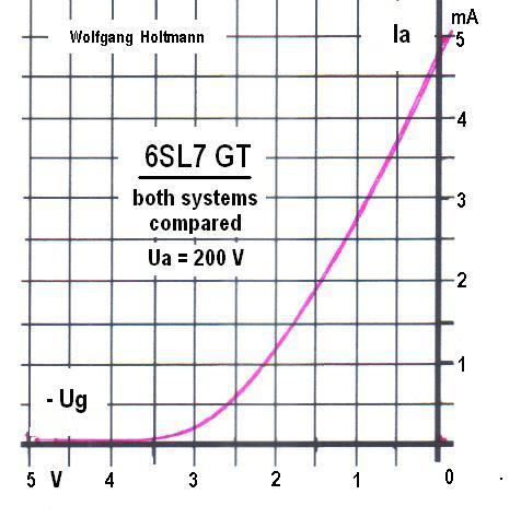
Fig.5
It goes without saying, the data of the chosen substitute can’t be compared with the original Wunderlich-B. Hence the measured voltages will differ from the original circuitry. I believe, it should be alright for the experiment.
For the additional diode, any diode will do.
The Wunderlich-B test circuit
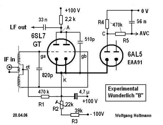
Fig.6
The experiment was focused on the Wunderlich Detection principal with the “amplified and delayed AVC”. For this goal, I reduced the setup to the bare minimum as shown in Fig.6
An unmodulated HF-signal is applied to the IF in socket. With an oscilloscope connected to the combined anodes, the centercoil is carefully adjusted to minimum ripple (equal amplitude at ga and gb) of the remaining HF. The purpose of the 510 pF capacitor is to reduce these remains. The LF signal is available at the anodes for further investigation.
The original audio-choke was substituted with a 2,2k resistor. The former resistors R2 is made adjustable whilst R3 is fixed to 39k.
As in reality, the cathode of the extra diode (6AL5 = EAA91, EB91, only one part used) is electrically connected to the main cathode(s). We find at the anode the two resistors R4 and R5.
Measurements
(All DC voltages measured with a tube voltmeter (Ri 10 M) against 0 V.
IF input no sign. weak sign. strong sign.
U ~ (volts) ct vers. ga 0 0.25 0.74
U (volts) across R1 - 0.4 - 0.5 - 1
U (volts) at K + 5 0 - 16.6
U (volts) at AVC 0 0 - 16.0
Because of the greater transconductance of the 6SL7 GT, a bias change across R1 of 0.6 volts will cause a voltage swing of 21.6 volts at the cathode. Indeed, an amplified AVC! Mind the threshold for the AVC. Below a certain IF input voltage, the AVC will not change at all!
What are the detector qualities of the Wunderlich circuitry ?
Of course, the LF-out fidelity is of great interest too. Unfortunately, I don’t have a genuine Wunderlich tube for the experiment. To my regret, I can’t make any rational judgment on this matter at the moment.
All Wunderlich Detectors have the same peculiarity. The bias (voltage across R1) for the triode audio amplifier depends on the strength of the received signal and can vary significantly. On the other hand, for amplification with low distortion, the bias should not vary too much from the midpoint of the linear part of the Ia/Ug curve. Was this assured by choosing a low gm figure (flat slope) on purpose?
I hope to give an answer to the still open question in the near future…
Wolfgang Holtmann
Annex
From the Arcturus Data Sheet, May 1932
Uf If
Wunderlich-A 2.5 V 1.0 A
” -A Auto 6.3 V 0.4 A
“ -B 2.5 V 1.0 A
“ -B Auto 6.3 V 0.4 A
Important: all four tube types have the same characteristics rated below!
Ua 250 V,
Ug - 16.5 V (both grids tied together)
Ia 6.5 mA
gm 950 µmhos (S = 0.95 mA/V)
mu (µ) 9.5
Ri 10 kOhm
Note: Both B-types were waived from the September-Catalogue of the same year!
To thank the Author because you find the post helpful or well done.
Now I have a WUNDERLICH too !
With some luck I purchased a used Wunderlich-A in the
Preparations
At first, I had to assure the good function of my tube. With an X-Y Plotter the static characteristics were fixed on paper. The reference data, as published by ARCTURUS, is annexed to the foregoing post.

Explanations: gebraucht = used; beide Gitter parallel = both grids tied together
With Va = 250V (in red) and Vg(a+b) = -16.5V the anode current reads 5.8 instead of the nominal 6.5mA, which is approx. 10% less. This is also true for the static gm figure. To my opinion, not bad at all and might even be caused by production fluctuations!
In green you will find another trace taken with Va = 150V. This enables us to calculate the Amplification Factor and Plate Resistance too. These values are also quite close to the published data.
Furthermore, a function test of each single grid is of interest. The idle grid was connected to the cathode. Due to mechanical differences in the grid arrangement a certain unequality is visible (blue traces) which had no repercussions on my experiments!
The Experimental Set-up


Explanations: ZF = if; NF = lf
The Wunderlich Circuitry was only used as an am-detector, combining the function of full wave rectification, audio amplification and also producing an adequate voltage level for Automatic Volume Control (AVC). This means, relative high if-amplitudes are to be handled. An application as a low signal “(double) grid leak detector” is not known to me and was not proposed by the inventor either.
To achieve the above mentioned goal, an hf-signal was fed to the circuitry which can be altered in level and in modulation depth (at 400 Hz). This should be sufficient to simulate realistic receiving conditions.
My test generator isn’t able to produce a high level signal to feed the Wunderlich Detector directly. Therefore, an additional amplifier stage was incorporated comprising an EL95 (6DL5) in low distortion operating condition. The output match is realized by coupling in series resonance.
I saw different circuit drawings with the Wunderlich Tube and regard a 100 kOhm load resistor and a supply voltage of approx. 250 volts as standard.
With this information I made another plot of the tubes transfer characteristic (Kennlinie), showing this time the dynamic behaviour of the triode.

Explanation: Ra = Load Resistor
Direct Comparison
This was done by comparing the NF at the anode with the modulated envelope of the injected HF on the screen of an oscilloscope. In the best case, no differences should be visible! The advantage of this method is, the slight imperfect modulation of my test generator has no influence on the judgements made. With other words: It doesn’t matter how the envelope looks like, the NF-output trace should match exactly with one side of the modulated HF. What’s more, as long as no significant deviations are visible, our hearing wouldn’t discover this as a distortion either!
Assuming a peak modulation depth of 30 to 40% may be regarded as normal (or average?) in the 1930’s, some stations might even reached 70% in the peaks. I’ll return to this later.
The Measurements
The pictures indicate the modulation depth m (%) and the voltage drop across resistor R1. The latter is also the bias for both grids (Ug(a+b) in triode function) and being used for AVC purposes as well. Underneath, the lf-out voltage at the anode is given. The term Vpp (= peak to peak voltage) is used to prevent false interpretation of non-sinuous waveforms.
1. Weak Reception


Anode: 0.55 Vpp
The left picture with m 34% shows no deviation. This is not the case for the 70% modulated hf on the right picture. When the carrier drops to its minimum, the lf-output can’t follow accordingly!
2. Moderate Reception


Anode: 35 Vpp
The bias is -4V. With m 34% on the left picture the demodulation is perfect. With m 70% the lf sine wave follows the envelope quite nicely too.
3. Strong Reception


Anode: 92 Vpp
With m 34%, again, no distortion is visible. The bias of -16.5V shifts the operating point to the middle of the curve. Nevertheless, with m 70%, this time the sine wave is flattened in the part of the carrier wave’s maximum! This will certainly cause audible distortions!
My Verdict
The proposed “New High Quality Detector ...ideally suited for use in modern super-heterodyne receivers” (N.E. Wunderlich, USA, 1931) offers good results with stations using a max. modulation depth of 40%.
When it comes to reception of high modulated transmitters, extra attention should be drawn to the applied hf-level. During my experiments it turned out, the optimal bias voltage (across R1) should be within the range of
Having read several publications on the subject (Credit to Ludwell Sibley, TCA), the Inventor was well aware about this limitation! He emphasized the need of an Automatic Volume Control Circuitry. Although he didn’t mention the maximum magnitude of carrier modulation allowed, he stated instead “… the voltage at the detector input is always held (due to AVC) at the one level where best demodulation is secured.”
One last Request
I have to admit, it is hard to find any reliable information about the general modulation percentages for the transmitters used in those days. Neither for
Who can help?
Wolfgang Holtmann
To thank the Author because you find the post helpful or well done.