Reconing of vintage Crosley Speaker
Reconing of vintage Crosley Speaker

Recently I've got a beautiful Crosley radio from 1934, model Fifty-two, Ch-5C2, but badly damaged. You can see it in my collection at RM. I began its restoration with reconing its electrodynamic speaker.This is an early type, model 214B, with field coil, hum-bucking coil and, of course, the voice coil.

The output transformer is mounted on speaker frame.

It was corroded, the cone was torn with missing parts, magnet gap full of dirt and some of leads broken .
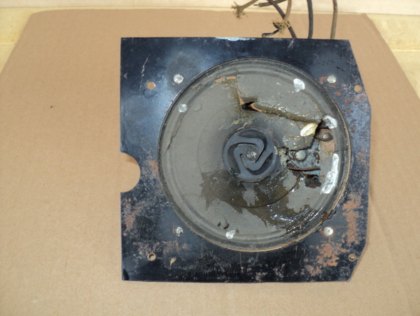
To begin with, I had to disassemble the speaker. First I cut off what is left from old cone, desoldered the voice-cone leads, removed the central spider screw and removed remnants of the cone with attached voice-coil carefully, not to damage the coil. Using surgical blade Nr 11, I removed all peaces of the cone from the coil body and the spider, so that they were separated.

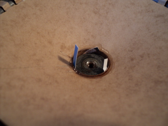
Windings of the voice-coil are temporary fixed with masking tape because they are wound to the very edge of the coil-form and were a bit loose. Later, I fixed them with thin layer of "crazy glue". This is important because all force which moves the coil and the cone is generated in the windings wire which therefore has to be firmly attached to the coil body. The spider itself was made of 0.6 mm thick pressed paper and its central hole is 5mm. As the screw is about 4 mm, it is possible to do some fine adjustments in centering after everything has been fixed. Fig. 5 shows the complete spider set.

The hardware is shown here.

I cleaned all parts and treated them with an anticorrosion fluid. The original back-side gray paint was preserved. All coils and output transformer were checked for open circuit and some leads had to be repaired.

And now comes the most important part - the new cone. First, I found an suitable material - transformer insulating paper, 0.15 mm thick, and then performed all necessary measurements: diameter of the speaker basket (124 mm), front opening of the cone (D1=100 mm), central opening of the cone, where the voice coil has to be fixed (D2=19,7 mm). Actually, the outer diameter of the coil has to be measured. The angle of the cone has to be determined (alpha=27 deg., cos=0.891). To calculate the cone I have found great help in two articles: "Speaker Cone Math" by Mark Palmquist and "Replacing Early Paper Speaker Cones" by Larry Weide. So, I calculated and cut out the flattened cone.

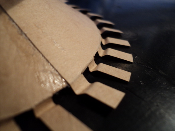
The calculated values were: outer diameter: 124/cos alpha=136.2 mm, cone front opening diameter: D3=D1/cos alpha=112.2 mm, central cone opening diameter: D4=D2/cos alpha=22 mm and the angle of the pie-shaped cutout : beta=(360 - (360*D2/D4)) = 37.6 deg. Before cutting away this section, I left and marked a 6 mm glue-lap. From the edge of the flattened cone I made numerous cuts at 4-5 mm distance, to the marked cone diameter (112.2mm). After that was done, every second tab was cut off to make vibrating of the cone easier. Those spaces could be covered with some elastic material (of surgical gloves, for example), but this is not a Hi-Fi device and is not really necessary. Then, the paper was carefully bent and glued to the mark-line with a nitrocellulose-glue. To get a flexible fixation, I creased all the tabs.
Central opening was trimmed to the exact diameter of the voice-coil using a cone-shaped grinding stone.
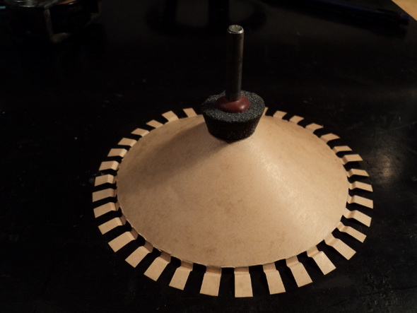
It has to fit firm, at first without any glue!

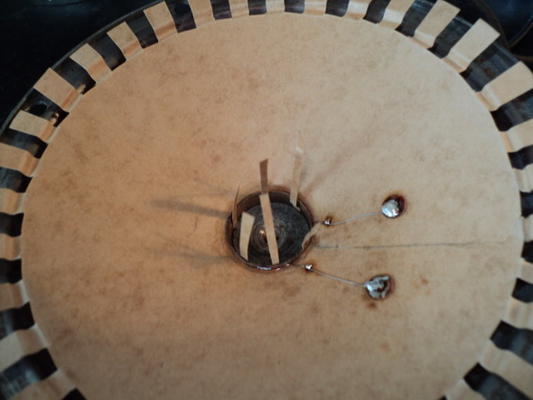
Note here a paper inside the coil! It has to keep equal distance from the inner magnet pole at 0.15 mm. This photo
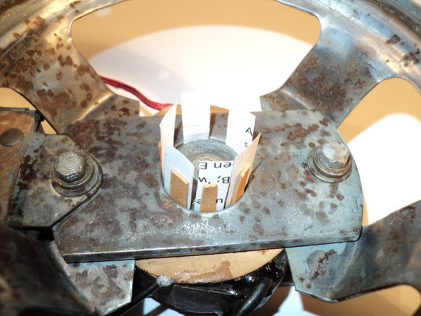
shows reassembling of the speaker. After putting field- and hum-bucking coil in place, the basket, the output transformer and the front magnet plate were fixed loose! First I had to adjust an equal distance between both magnet poles. By my speaker, the gap was 0.8 mm. The coil is 0.4 mm, so the clearance between coil and both magnet poles has to be 0.2 mm. When the distance of 0.8 mm was secured using some cardboard and paper, both screws were tightened firmly. Now the voice coil was fitted into the cone with both wire endings at front side, the cone was centered to the inner magnet pole with 0.15 mm thick paper strips, and cone was temporary fixed to the speaker basket.

Adjust the depth so that only 2 or 3 turns of the voice coil winding are visible above the magnet plate. Now the coil body has to be glued to the cone. This joint has to be the strongest one, so I used two-component epoxy resin.
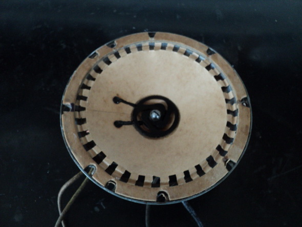
After I let it to cure for 24 hours, I put two brass hollow rivets of 2 mm at about half a cone radius. Two peaces of 0.2 mm bare wire were hammered under the brass washers and rivets and soldered to the voice-coil wire ends.

On the back side I soldered two flexible leads, being braided desolder-wick 1mm thick, 5-6 cm long.

When all that was done, I put the cone back on the frame, centered the voice coil again,
checked the depth of the coil,

put some elastic glue (neoprene) on the frame rim , another layer of glue on the gasket and after a few minutes drying, pressed all that firm together. After cure, the rivets and their connecting wires are covered with black nail-polish. Then I removed the centering strips of paper, fixed the spider and glued it to the cone, also using the strong epoxy.
After cure, centering has to be checked! The coil must not touch the magnet poles! If it does, loosen the central spider-screw and slide the spider a bit aside until it doesn't and tighten the screw again. Then, the original repainted metal front plate was put back. Finally, I soldered all leads to the contact plate on the output transformer.
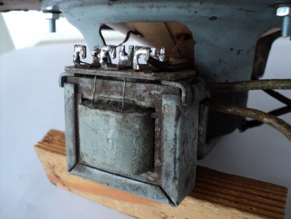
The hum-bucking coil is connected in series with the voice coil to the secondary of the transformer. Keep the original polarity of both coils- they must be in opposite phase to buck the hum! Now, the time has come to test the whole work. First, I checked the field coil using my lab's power supply.

It was OK : 90 V / 30 mA. To test the frequency response, I used the sine-signal from my signal-generator, amplified by a simple test-amplifier with ECL82, connected to the primary of the original output transformer.

The first test was at lower range 40-650 Hz. It was OK, and resonant frequency was about 140 Hz.
Second test was at higher range and the speaker responded nice from 650 up to 8000 Hz - more than enough for the BCB.
As the final test, I fed the audio signal from my Standard Transistor Radio to the amplifier and I was satisfied with the sound.
All that was a lot of work, but I find it worthwhile. If some of you has done something similar, I would appreciate any comment or advice.
To thank the Author because you find the post helpful or well done.