Replacing old capacitors
Replacing old capacitors

When planning to restore old radio sets, common questions are: ‘How many capacitors should I replace?’ or ‘Should I replace all capacitors to prevent faults?’. I read of people that dismantled their radios to replace everything inside, finding themselves with nice cabinets full of shining parts, but showing erratic operations or not working at all. In my experience the substitution of properly working parts with more or less similar components is useless, may impair the operation of the equipment and may also result in additional failures. Original components, when still good, are stable and not subjected to infant mortality. Of course everybody has his own opinions derived from past experiences. Nevertheless answers may vary depending upon several reasons: quality of the design with proper use of right components, type and quality of materials, environmental conditions during life and storage of equipment. I see frequent discussions tied to specific models. Since almost every collector of old radio equipment may be interested in this topic, I decided to open a generic thread, hoping that readers would add their experiences.
Common faults due to old capacitors
Capacitors are responsible for many of the failures arising when trying to operate old equipment, grouped in the categories below.
1) Short circuits.
A short can be easily identified by low voltage and/or resistance values all around the faulty section. Often shorted caps cause other faults, as burned resistors or blown fuses. Whenever one of the latter conditions is encountered, shorted capacitor should be suspected unless different cause is found.
2) Opens.
This failure is common in electrolytic capacitors, when fully dried. If faulty capacitor is in the B+ filter section, a loud hum will arise. In some circumstances, such as in the cathode path of audio power amplifier tubes, a dried capacitor could also give benefic effect on sound quality. Opens can also be occasionally found in some polystyrene foil capacitors, due thermal stress on the leads.
3) Drifts in capacitance value.
These may derive from different causes: partial drying of electrolyte in aluminum capacitors; drying or alteration of impregnating oils or waxes in paper capacitors; moisture adsorption in ceramic or in paper dielectric; small cracks in silver coating of some lacquered mica capacitors, partial chipping of ceramic capacitors. A twenty-percent decrease in the capacitance of filter electrolytic capacitors may be tolerated, but a five-percent variation on the value of ceramic capacitors in tuned RF circuits may move resonance out of tuning range.
4) Excessive leakage or low insulation resistance.
A very high, but finite resistance value can be measured across any capacitor. In paper capacitors low resistance may be found because of moisture adsorbed by paper itself. Some leakage is acceptable in many circuits, as in decoupling paths of B+ distribution or in low voltage sections. In other cases, as in the coupling between AF driver and AF power amplifier stage, leakage can move grid biasing of the power tube to positive values.
In electrolytic capacitors leakage is due to small holes in dielectric oxide. Leakage current starts quite high when capacitors have been left inoperative for a long period. In this case, if full operating voltage is suddenly applied, leakage current may cause irreversible failures. The dielectric layer can be easily repaired by a short reforming cycle.
Dielectric types in old equipment
Paper foil – Paper, usually impregnated with wax or oil, was used for general-purpose capacitors, ranging from about 1000 picofarads to over than 10 microfarads. It is still in use today, also in addition to plastic films, in many a.c. applications. Good paper capacitors stay still stable after over than 70 years. Some types or lots may give troubles in the years, due to poor hermetic sealing of their bodies, to poor manufacturing process or to unstable or hygroscopic impregnating fluids.
Pic. 1 – Overview of paper capacitors. P1, P2, P3 and P4 are very poor types, with glass bodies and tar sealing. P1 and P3 show melted seals and P1 even lost its impregnating wax. P2 shows unstuck tar seal, P4 has swollen seal. P5, P6 and P7 are paper capacitors with molded bodies, sometimes hygroscopic through lead seals or small cracks. P8 is an excellent paper capacitor made around the mid ‘930s, with bee-wax coating: I performed 12 random checks on the many units used in my Hammarlund SP110 (1937), always reading insulation resistance values higher than 100 megaohms.
Pic. 2 – Although looking as paper types above, capacitors P9 to P12 use plastic films and insulation resistance is in the order of one gigaohm: no need for replacement, unless really defective! P13 shows an old paper capacitor with phenolic or rubber molded body: same look of many mica capacitors, but doubtful insulation if, since the ‘930s, Aerovox knew how critic the body molding process could be!
Mica – Mica, usually with silver armatures, was common in high-stability RF circuits. Body evolved in the years from molded thermoplastics to dip epoxy, but in Europe some types were just lacquered or even unprotected at all. Molded and dipped mica capacitors are usually reliable in the years.
Pic. 3 – Mica capacitors. Usually very reliable, particularly types M4 and M5. Some lots of the M3 type can be found out of tolerance, when silver layers are cracked and partially insulated from the leads. Note that the block packages of types M1 or M2 was also used for paper film capacitors: the identification of dielectric for capacitors with rectangular cases is not easy for capacitance values greater than few nanofarads.
Polystyrene (Styroflex) – Polystyrene film has low dielectric losses and good temperature stability. Polystyrene capacitors have been used in Europe as precision and stable components in RF and IF tuned circuits and in AF filters. Unfortunately this film does not withstand temperatures in excess of 82ºC and for this reason mica was preferred in United States. Reliability is very high, unless capacitors had been damaged by overheat.
Ceramic – Ceramic capacitors were available for a wide variety of applications. Depending upon their composition, ceramic materials with different dielectric constant and controlled temperature coefficient were made. Low-capacitance, controlled temperature coefficient types have been commonly used in RF or IF tuned circuits. Medium to high capacity types found applications in interstage coupling or in RF decoupling filters. The reliability of ceramic capacitors is very high, although in some cases their capacitance may be altered by adsorbed moisture; usually capacitance recovers its value after a short baking.

Pic. 4 – C1 is a polystyrene capacitor. C2 to C4 are typical ceramic capacitors.
Electrolytic – In electrolytic capacitors a thin oxide layer acts as dielectric between aluminum foil inside and electrolyte paste. Electrolytic capacitors are usually polarized and oxide may easily be destroyed by polarity reversal or by overvoltage. Common failures include oxide perforation or shorts, often triggered by excessive leakage currents, and low capacitance, due to dried electrolyte. Electrolytic capacitors should be replaced if their capacitance falls under 80% of the nominal value. The oxide layer can be partially etched when the capacitor is left inoperative for a long period. The oxide layer can be reformed, applying a reduced voltage for a while, in order to limit leakage currents to safe values at the beginning. Otherwise excessive currents may cause harmful temperature rise with electrolyte escaping from the vent hole and further current increase, up to the destruction of the oxide layer.
Pic. 5 – These capacitors show visible traces of electrolyte leakage and should be replaced.
Some tips
Capacitance meter and insulation meter are usually required to trace faulty capacitors. Common multimeters are useless to measure insulation resistance. No need to buy expensive instruments, since approximate measurements give a good indication of the fault. I found suitable insulation meters at absolutely affordable prices here.
When measuring the value electrolytic capacitors, one should remember that –20 to +80% initial tolerances are quite common for these components.
When first handling any old equipment it is advisable to perform some preliminary operations before replacing components. After a good cleaning, a visual inspection returns a first list of damaged parts, as hardened rubber cables or cracked capacitors that must be replaced before power-up. As general rule, if the equipment was stored for a long while, six months or more, regardless of its previous operative conditions, a soft wake-up procedure should be run to allow reforming of electrolytic capacitors and of selenium rectifiers, if any. It is advisable to run equipment at about half voltage for half an hour, monitoring B+ voltage and watching for fluid losses from electrolytic capacitors, for overheat of components, hum and other alarming conditions.
No need to replace all capacitors. Some are used in low voltage, medium to low impedance paths and their operation is not impaired by small leakage. Good prewar paper capacitors still today have an insulation resistance in the order of several tens or hundreds of megahoms. Other capacitors, looking more or less as paper ones, use mica or plastic films and their resistance is in the order of 1000 megahoms.
The replacement of paper capacitors requires careful evaluation of the circuits where they were mounted. Paper dielectric material performed fairly well in AC applications: polyester film is not as good as paper in the same job. Whenever possible film-foil or polypropylene film capacitors in a.c. applications inside the equipment should be preferred. It is the case of capacitors across the primary winding of output transformers, of small a.c. motor run capacitors or of filter capacitors across high-voltage windings of the power transformer. In power line filters only UL/CSA/IEC approved film-foil or ceramic capacitors should be used.

Pic. 6 – Some X2 film-foil capacitors approved for safe use across a.c. power line.
In the case of push-pull output stages, when replacing a capacitor in the circuit of one tube, it is advisable to select a matched pair and replace also the corresponding capacitor on the second tube.
Low-value capacitors used in RF or IF stages can be ceramic, mica or, in Europe, styrene film (styroflex) are very reliable with the exception of some lacquered mica types. As general rule RF capacitors should not be removed or moved from their original seating, unless definitely defective. When available, dipped mica is the best replacement for other types, with the exception of temperature-controlled ceramic ones, as N220 or N750 sometimes found in temperature compensated resonating circuits. Obviously resonant circuit needs to be aligned again after having replaced the capacitor.
The diagram below, referring to a typical small audio amplifier, helps to illustrate how to replace old capacitors according to their applications. Here we have C1 and C2 as B+ filter capacitors, C3 used across the power line, C6 used in low-voltage signal path, C7 in critical interstage application and C8 operating at audio frequencies.
A short in C1 or in C2 usually causes burned or opened X1 and/or R1. C1 and C2 must be replaced if defective or when value is under about 40 microfarads per section. C3 must only be replaced by X2 film-foil or ceramic approved types. C6 usually does not require replacement, unless open. C7 should be always checked for low leakage, or the grid of the output pentode may be driven positive and the pentode itself will be browned in a short while. The simplest way is to measure for zero grid voltage on TP1, with the tube removed from its socket. A metallized polyester type can be a suitable replacement for C7. Due to dielectric losses, C8 is subjected to dielectric heating in normal operation and may eventually look like P1 or P3 in Pic.1. Metallized polyester types are not reliable as replacements for C8; film-foil or polypropylene types will safely handle the audio frequencies available across the primary winding of the output transformer.

Pic. 7 – Schematic diagram of a typical audio small amplifier.
To thank the Author because you find the post helpful or well done.
Other capacitors working in critical conditions.

Hello Emilio, my congratulations for this extremely useful paper.
I might just add that sometimes capacitors have been placed to work under unsuspected critical conditions in circuits that are usually considered of secundary importance. One of these is the tone control. In some cases, the tone control is placed directly after the power otput stage and is formed by a series of a variable resistance plus a paper capacitor directly connected to the plate high tension. I have found this type of circuitry in the Phonola 731 among others. In these cases, if the capacitor leaks or shorts, all the plate current may pass through the tone variable resistor causing extreme overheating and, eventually, failure or fire. If the radio under repair has such circuitry, the tone capacitor must be checked immediately with great care.
To thank the Author because you find the post helpful or well done.
Capacitors across power line
One of the less known issue, when replacing capacitors connected to the power line in old equipment is how to select the proper replacement. These components are very critical indeed: any wrong substitution may cause harmful electrical shocks, fire and other damages.
Many years ago the selection of these components was left to competence and discretion of the manufacturers. Many times empiric rules were followed, as specifying 5 or 6KV insulation. These rules made possible the use of very poor and unreliable capacitors that had got through a single pulsed insulation test in the favorable conditions of their factory. Safety rules today impose the use of approved components that must be selected according the circuit and the line voltage.

The above draft illustrates when class Y or X capacitors should be selected according to their connections. As mnemonic rule, X stays for ‘across’ the line, as in (b). Y types are used from a usually floating line to the metallic chassis and must grant safe leakage currents. X or Y are followed by a figure indicating their test voltage, usually 2 (2.5KV test) for common uses. Even if their final result may be very similar, the behavior of X and Y types during the failure may be quite different. These components have usually approvals marked on the bodies.
To thank the Author because you find the post helpful or well done.
Capacitor Replacement
Thanks for all the great information Emilio. One of the most common mistakes on changing caps ,is this: Change caps one at a time...test your radio after each cap is replaced. Do Not change all at once then power up...If you mis connected one, you will never find it ( or will cost you much time to do so) By changing one at a time, you will isolate the defective cap and be able to check that section for possible resistor problem ( connected to the defective cap) and always change the filter caps first. If a radio has not been tampered with by someone else, most repairs will be solved by this method......Thanks AL
To thank the Author because you find the post helpful or well done.
Paper capacitors: another example
To better illustrate the guidelines to replace old paper capacitors, here is the diagram of a classic superheterodyne radio. For better readability, RF coils and band switch have been omitted. This diagram was selected because it also shows a grid biasing solution common to many old radios. The circuit uses 6TE8, 6K7, 6Q7, 6V6 and 5Y3. I added arbitrary names to some capacitors, resistors and supply lines referenced in the text.
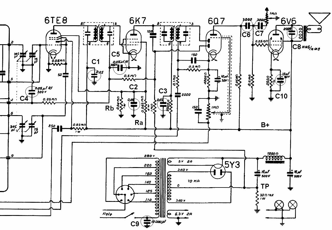
The plate and screen grid voltages to converter and IF amplifier tubes come from B+ supply through a power distribution network including C1, C2 and C3, all 50 nF. The control grids of the same tubes are biased by AVC signal, from the lower diode of the 6Q7, superimposed to the fixed negative voltage present across the 30 ohms resistor, in the point labeled as TP. In grid-biasing network we find C4 and C5, 50 nF each. We also have other paper capacitors. C6, 3 nF, couples the audio preamplifier to the control grid of the power amplifier tube; C7, also 3 nF, is used in a low-pass filter on the 6V6 grid; C8, 2 nF, is in parallel to the primary winding of output transformer. C9, 10 nF, is connected from the power line to the insulated chassis.
We can assume that B+ supply is around 300V. Any capacitor showing high-voltage insulation resistance in the order of a couple of megaohms is usually considered very bad. But, if insulation resistance is about 2 megaohms, just a feeble current not larger than 150 microamps can flow through each capacitor, C1, C2 and C3. Such a current has no effect at all on the converter plate path, being C1 directly connected to the B+ supply. Capacitor C2 is in a sort of voltage divider formed by Ra (25 kohms), Rb (40 kohms) and the equivalent load given by the screen currents of hexode section and of IF amplifier. If tubes were operated according to their specs at 100V, we can assume a current of 8 mA in the resistor Ra (5.5 mA through the grids, plus 2.5 mA through Rb). The effect of an insulation resistance as low as 2 megaohms in parallel to Rb may then calculated in about 400 millivolts decrease of the screen voltage. This negligible variation does not affect the proper operation of related stages. Even in the case of C3, if its insulation resistance is around 2 megaohms, less than 0.4 V drop can be measured on the plate of 6K7.
No fears about the life expectancy of capacitors that show insulation resistance of few megaohms. In most cases, when small punctures of dielectric occur, paper capacitors have good self-healing properties. Then, in the examined high-voltage circuits there is no normal reason for replacing capacitors showing some small leakage.
Of course, this is not always true. In other cases, limiting resistors on screen grids may have values of 220 Kohms or higher and a capacitor with leaks in the same order of magnitude as above may cause excessive voltage drop.
Now let us examine the decoupling capacitors C4 and C5 in the grid biasing circuits of the same tubes. They operate at very low voltage: -2 volts fixed bias minus the AVC. In this condition, according to the Ohm’s law, no appreciable current can be flow through even a 2 megaohms insulation resistance. Moreover the resistance across the capacitor at such low voltage is much higher than the one measured at high voltage. This because no surface arcing and similar phaenomena may take place in this condition. Anyone can easily verify with a normal multimeter that the low-voltage resistance of otherwise leaky capacitors is generally over than 20 megaohms (infinite). The leakage currents of C4 and C5 can then be estimated in the order of tens or hundreds of nanoamperes! We may conclude that these capacitors should never be replaced just because of their age.
C6 is very critical, as we already saw in the previous example, and must be checked for zero voltage from the grid pin to chassis, with the 6V6 removed. About C7, used in a low-voltage path, the same considerations already made for C4 and C5 apply. C8 may overheat and lose insulation when the radio is operated at high volume for a long while. If defective, it may be replaced with a polypropylene type.
C9 is another critical component: the original part may be left only if no cracks or defects are visible in the body and the insulation meter reads infinite resistance at 500V or higher test voltage. Otherwise it must be replaced, in this case, with a class Y approved type.
Just few words on the interaction among the proper operation of C6 and C10 and the sensitivity of the radio. The grid bias of the audio power beam tube 6V6 is important not only for the proper operation of the output stage, but in this case also for the operation of the controlled mu mixer and of IF amplifier. If C6 is leaky or C10 is shorted (rare but not impossible), 6V6 may drain a large current, until the saturation of the 6V6 itself or of the rectifier. This large current, flowing through the 30 ohms resistor, results in a wrong value of the grid bias voltage on TP.
Initially, when cathodes are still efficient and capable of strong emission, voltage goes more negative than usual. In addition to a distorted audio, poor sensitivity can be observed, since the operating point of RF and IF tubes is moved toward the cut-off region. But if the radio is operated in these conditions, both the power audio amplifier and the rectifier tubes are rapidly damaged. As emission of the rectifier or of the power tube drop, also the bias voltage on TP moves toward zero. In radio sets that use similar biasing circuits, if at a first check the audio is distorted and the sensitivity is poor or if a poor sensitivity can be observed, a leaky coupling capacitor to the power amplifier tube should be suspected.
To thank the Author because you find the post helpful or well done.
? replacing capacitors

My reasoning for replacing any suspect capacitors is based on my limited knowledge and something I had been told which seemed to make sense: No testing will reproduce the conditions found in the circuit operation , therefore cannot predict if is effectively causing fault.Perhaps the insulation tester you mention is the answer, I did not know of these!
To thank the Author because you find the post helpful or well done.
Fault trace strategy
Dear Stuart,
the insulation tester is a useful tool, provided that you are capable of correctly evaluating its readings. In some circuits if you read well over 50 megahoms the capacitor must be replaced. In other circumstances capacitors returning less than 10 megaohms are absolutely acceptable. In low voltage signal paths the insulation tester is useless.
What is important is the fault trace strategy. First of all you should start assuming that the equipment you are servicing was performing well during its life, since it left the factory. It had been manufactured by skilled people and every component had been carefully selected by a staff of experienced designers and engineers. Hence you should simply find the faulty component, replace it and check that the problem was definitely fixed. If you start assuming that everything inside is bad just because aged, then you can simply skip this article and buy a new shining plastic radio.
You should try to approach one fault at a time and isolate the defective zone with voltage and resistance measurements. Then, if a capacitor is responsible for the fault, you can easily identify it simply comparing the actual measured values with the expected ones. If the fault tracing was correctly performed, usually you find only one bad capacitor to replace in that circuit. At this point, the insulation meter can be helpful to have your diagnosis confirmed. By the way, the insulation meter can be also useful to check the insulation of transformers, sockets, cables and, more important, of the chassis with respect to ac mains.
To thank the Author because you find the post helpful or well done.
? learning
Now Im confused , shouldnt DC insulation for a capacitor ideally be infinity , therefore would be acceptable only if over a certain value of ohms?
This is certainly a learning experience, which is good as it is about time I learn more to enable me to do things properly having been fiddling with old valve equipment since I was a teenager. I bought a book :Valve radio & Audio repair handbook,Chas E Miller,Newnes publishing,Oxford 2000. Any other suggestions?Perhaps you have written one? I am learning a little more about amplifiers but do not understand as much as I want to, and have no idea yet about tuning stages.
I have only a multimeter, will need something more, not sure exactly what, the book suggests a signal generator,which sounds important for tuning stages, but does not mention insulation tester.
The next one I have to work on is a Telefunken Opus 55 TS, Yes I finally found one with push-pull! I would like to go about restoring this one properly, but dont quite feel equipped to do so with knowledge and equipment.
Regards Stuart
To thank the Author because you find the post helpful or well done.
C Insulation Tester

Dear Stuart,
do not be confused, it is necessary to find the critical junctions only, as Emilio well described. It is easy, in the schematic we can add concurrently to capacitor 10MOhm resistor and calculate what happened. For example between previous anode and next grid: the previouse anode voltage is usually between 80-250V, grid voltage is usually -3 to -15V, grid resistor has usually value 0,5-1MOhm. Thus we will get voltage divider 1:10 or 1:20, it means the grid voltage could be pozitive and not negative, the tube is opened fully, might be demaged too. You can see, not only 10MOhm but 50MOhm insulation can be sometimes critical too!
About easy insulation testers you can read in thread http://www.radiomuseum.org/forum/isolationswiderstand_von_cs_pruefen_eine_vergessene_methode.html
Gabriel
To thank the Author because you find the post helpful or well done.
Insulation resistance
Dear Stuart,
my hints are generic and cannot substitute the direct experience on each faulty equipment. I am just highlighting that a methodical and careful approach is required and how old capacitors can be replaced when faulty. As I said before, first of all you must have confidence in the manufacturer of the radio you are servicing. Then, if you have a normal tester, use it to fix the problem. I already explained how the check of the coupling capacitor between the audio driver and the power amplifier tube could be performed simply removing the power tube and measuring the voltage on the control grid pin. Similar checks can be run for instance on screen grid decoupling capacitors, measuring for current flow with the tube removed from its socket: Voltage must be the same at both ends of the screen grid resistor. Sometimes, when I pick an old stock paper capacitor for replacing a bad one, I use the insulation meter just to check the new capacitor.
The insulation resistance of capacitors can never be infinite, the value depending upon the dielectric material, its thickness, the temperature and its surface, related to the capacitance value. The table below, from Radiotron Designer’s Handbook and referred to metal-can types, gives the initial insulation resistance for DC paper capacitors, according to the R.M.A. Standard TR-113.
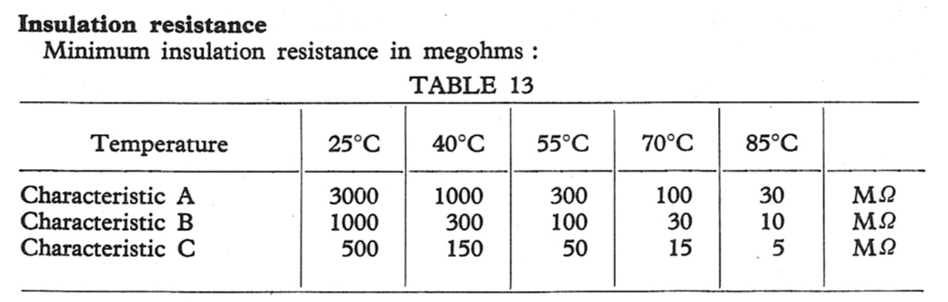
Of course, in non-hermetic types, actual values decrease through the years due to some moisture adsorbed by paper. Nevertheless any skilled designer, when approved a certain capacitor in a given place, should have calculated enough margins to allow stable operation when easily predictable parametric deviations should have occurred. In their job they relied upon technical documentation of the same passive component manufacturers and were certainly flanked by their many application engineers. Maybe this was not true for several Italian radio firms, but was certainly true for serious radio manufacturers from, say, Germany.
Today we do not have original data sheets of any old capacitor family and hence we cannot know even the nominal insulation resistance. So, if the insulation tester reads some 10 megaohms for a given capacitor, we can only evaluate if this value is acceptable in the specific circuit. Usually the Ohm’s law and some common sense should guide our evaluation. Then we give power and see if the circuit works. If not, the capacitor must be replaced even if it returns 1000 megaohms: in a precision sample and hold circuit, even this value can be too low!
Just a note about the books. Many old textbooks can give information about radio circuits. Some of the most comprehensive are:
- Radiotron Designer’s Handbook by Langford-Smith, RCA. Also available somewhere in CD.
- The Radio Amateurs Handbook, ARRL, around 1960.
- Radio Engineering by Terman.
- Radio Engineering Handbook by Henney.
Anyway these books can just give generic description of components, their related technologies and performances. Actual technical data of the various components could be only found in data sheets and catalogs of each manufacturer.
To thank the Author because you find the post helpful or well done.
Attitudes to replacing capacitors

Dear Emilio,
I was intrigued when I read about your experience with paper capacitors. Here in the UK there is a culture of replacing paper capacitors almost without question or so it would appear by reading posts on UK forums. This made me wonder if there are factors that influence regional or national attitudes/culture.
My first thoughts were of you in sunny Italy & me in rainy England. Could climate affect the failure rate of paper capacitors? Perhaps members from other cold wet countries could comment on their experiences.
In the UK many capacitors were made by an infamous company “Hunts”. These have such a bad failure record that many service staff would replace any capacitors of that brand found in a set regardless of their condition. This experience may have helped create an attitude of distrust for all old capacitors.
A similar situation appears to be happening with modern electrolytics. Many forums have posts about electronic equipment such as satellite receivers, router etc. failing due to short life of electrolytics. The common response is to change all such capacitors. Several companies make repair kits for specific equipment, which comprise of replacement electrolytics only. Maybe there is a problem with manufacture of such components, or perhaps these are the only components that can easily & cheaply be replaced. Either way this re-enforces a culture of “change the capacitors”.
Personally I prefer to follow a traditional fault finding process to identify faulty components. When restoring vintage radios I replace only those components that are faulty or hazardous.
Finally I wish to thank you for an excellent thought provoking post.
Regards
Keith
To thank the Author because you find the post helpful or well done.
Old types and modern trash
Dear Keith,
many thanks for your comments about the failure rate of some types and brands of capacitors. Here in Italy we have had a lot of manufacturers more unreliable than Hunts, such as Facon, Mial and the same Siemens Olap. Nevertheless the reliability depends upon many factors, including the environmental conditions through the years, but even the specific family, the production lots and sometimes the same application circuit. Of course we should also consider the class of the set and the average components existing in its age.
Almost any manufacturer listed several families of capacitors, some tropicalized or hermetic or even rated for operation at high temperature. The low-end production usually was run in secondary factories, often with poor materials and poorer processes, to save money. When talking of any dielectric type, as paper, electrolytic or mica, we are talking of a lot of different materials and processes. Paper was never used without some impregnating materials, oil, wax, resin or synthetic compounds. Armatures could be made by thin aluminum foils but also, in miniaturized capacitors, by metal sprayed or evaporated on the paper film. The case could consist of a cardboard, ceramic, metal or even glass tubing, sealed with tar, wax or epoxy, or could be a thermoplastic mould or even an epoxy coating. Consider how many combinations of paper, impregnating fluids, armatures and bodies could have been made. Any combination had its own characteristics and application ranges and, when trying new combinations, unexpected problems could have been fixed only after more or less prolonged production run. Another example is given by mica capacitors: top quality types were made using hard to find ruby mica, but the cheaper green mica did the same job in low priced types, until dielectric began to flake-off. In the life expectancy of electrolytic capacitors two factors are of paramount importance: purity of aluminum and body sealing. Well, I remember that by definition in Italy was considered as pure aluminum an alloy just containing 88% of this metal! And sealing is usually performed using rubber gaskets: but how many natural or synthetic compounds known as rubbers stay stable through the years?
With few exceptions, limited to dishonest manufacturers that could have just survived for a while in local protected markets, as happened with ANIE in Italy, it is crazy to decide anyway a preventive recapping of any old equipment. I do not understand this form of discrimination against capacitors. Other components fail, nevertheless nobody plans the preventive replacement of all the resistors or of the magnetic parts. We can only say, basing on our experience, that a certain family of capacitors from a given manufacturer could have higher than usual probabilities of failure, but this is only a probability. We should replace a capacitor, as well as any other components, just in two cases: either if it looks bad at a visual inspection, or it was found bad in a fault tracing.
My experience generally covers high-class equipment starting from WWII. Apart from the equipment I handled in some fifty years, still today I have hundreds of radios, receivers, amplifiers and test equipment with many thousands of capacitors inside, all properly working. As I wrote before, I have a 1937 Super Pro still with its bee-wax filled original capacitors (Note that the Radiotron Designer's Handbook suggest the use of wax-impregnated capacitors for plate to grid coupling). Just to talk of one group of instruments, I have 13 Tektronix vacuum tube oscilloscopes, all operating. I remember to have replaced just two capacitors out of the some 4500 used inside them. Many of my German radios still have their original capacitors inside. On the other side I found an impressive high figure of rejects in some high-class Italian-made Philips radios, as BI700A and DI700A. They were similar to the Philips NL model BX700A but used Italian made components, to save customs fees. Probably the Italian manufacturer was requested to build capacitors to the latest Philips specs, without having the necessary experience, machines or materials.
About the modern capacitors, I do not like modern equipment, modern components and modern assembling techniques. First of all 100% of modern components are made in Asia. The few times I saw a data sheet, it was in Japanese or in Chinese! Then I began to see hallucinating packages, such as the BGAs (ball grid arrays), where pins are all hidden under the package itself. Soldering of these components is performed in hot atmosphere reflow lines. You have no way to heat just the pads to be soldered. Here hot air is blown from both sides all over the surfaces of the board until the internal temperature, under the IC bodies, has reached about 220 degrees centigrade for more than 5 seconds. All the components are more or less browned by the soldering process but some of them, as SMD plastic or electrolytic capacitors do not survive this treatment. This is why companies already know the parts to include in the service kit.
Best regards, Emilio
To thank the Author because you find the post helpful or well done.
Misleading Test gear
Recently after a long gap I got an old 1950s radio to repair (or Restore?).
The most costly fault causing capacitor, between grid of DL96 and anode of DAF96 had already been replaced with what looked like a 1970s part.
But there was still four other Waxed paper capacitors of the kind believed to be faulty always in UK. The radio performance was erratic and poor.
I have one meter that tests up to 47M Ohms and is quite good. Also a Bridge and three electronic capacitor meters. The first wax capcitor I took out measured a little high on capacitance but measurable resistance at all. Just like an open circuit exceeding 47M.
But my Greyshaw Instruments CR50 bridge has a "real" leakage tester. It uses about 160V via several Megaohoms to one terminal and other terminal to a neon with low leakage capacitor. About 100M Ohms is 1 Hz flashing of "magic eye". With 10M ohms it flashes quite fast.
Testing the four remaining waxy capacitors all were OK on the DMM (> 47M), but on the 160V leakage tester the eye flashed very rapidly similar to a 2M resistor! With the replaced capcitors the radio was superb and HT current just under 6.5mA at 104V from the built in mains adaptor. (The Electrolytics all tested fine in circuit).
I think the fact is that in low voltage positions the Waxed paper (Waxys) may be OK, but with age they all 100% break down with higher voltage across them
So what do you do if you don't have a high voltage leakage tester? The Waxed Paper capacitors only "breaking down" at HT voltages not the 3V of modern meters.
All you need is an old camera with flash or a flash gun you don't want any more!
This will test at nearly 300V
1) Remove flash unit electronics from unwanted camera or gun
2) Remove flash tube and large capacitor (often 300uF 350V).
3) Fit a 400V 2.2uF or 4.7uF capacitor instead. Ensure polarity correct.
4) disconnect series resistor from neon.
5) Add 1M Ohm to end of existing resistor you disconnected from neon. Connect to a test Terminal "A"
6) put a low leakage 100V or more rated 100nF ceramic or foil (not electrolytic) across the neon and connect the end that used to have resistor to test Terminal "B".
7) Put in a little box with suitable battery and on/off switch. Cut off the trigger wires.
Testing
a) If you short the terminals the neon will flicker very fast.
b) If you put a 1uF capacitor the neon will light then flicker more and more slowly as it charges up till neon goes out. Now the test capacitor is charged to over 250V.
WARNING
While you can't get a shock from the tester or a faulty capacitor a larger value good capacitor may have a dangerous amount of charge and should be carefully discharged.
My "new" capacitors all pass on the box (neon goes out). Even ones rated only 100V! All the Waxed paper capacitors failed totally, neon on virtually solidly!
Conclusion
The above article is excellent in depth, but most non-specialist test gear doesn't have enough voltage to test capacitors for valve (tube) applications.
Early test of flash gun circuit

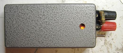
Completed box (lid is arranged as bottom)
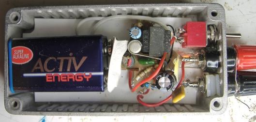
You can see lit neon at bottom and the new 400V or 450V 2.2uF or 4.7uF capcitor
(The original capacitor takes too long to charge)
Cut up Margarine tub as insulation under the flash gun circuit.
A Waxed paper cap failing
(previously I wrote a similar article here Vintage Radio and Television (VRAT) under an assumed name)
Attachments:
- Waxy on test. 2nd Neon is just power indicator (34 KB)
- inside-leakage-box (26 KB)
- leakage-test-on (25 KB)
To thank the Author because you find the post helpful or well done.
No need for special tools
Dear Michael,
I tried to explain that virtually all the capacitors have some leaks. I am quite conservative and in my opinion original components must be retained while the set, where they were mounted by the manufacturer, is still working fine. What is important in the restoration of an old electronic set is to understand when a component really must be replaced. The effect of the leakage on the circuit, rather than the measurement of the absolute leakage itself, is to be evaluated to take a decision. The insulation meter can help to understand what happened, after the problem was fixed, or even to prevent a probable future failure. Anyway, if I decide to measure the many thousands of capacitors I have in all my working sets and replace all the leaky ones, I should either book the entire one year production of a large manufacturer or, better, open a new plant to produce my own replacement capacitors. Yet all my sets work fine and just in the latest two months I restored four Tek tube oscilloscope, replacing only four capacitors, two were dried, out of some thousands.
I do not agree on the possibility of obtaining really useful information by a flashing neon. Anyway simple measurements can be run with ordinary instrumentation. For many paper capacitors the evaluation of their in-circuit behavior usually gives sufficient information to decide if any replacement is required. The job can be done with a simple multimeter and the result is even more reliable of any measurement made on the capacitor after having removed it from its circuit. The figure below shows the three basic DC circuits where a paper capacitor can be found.
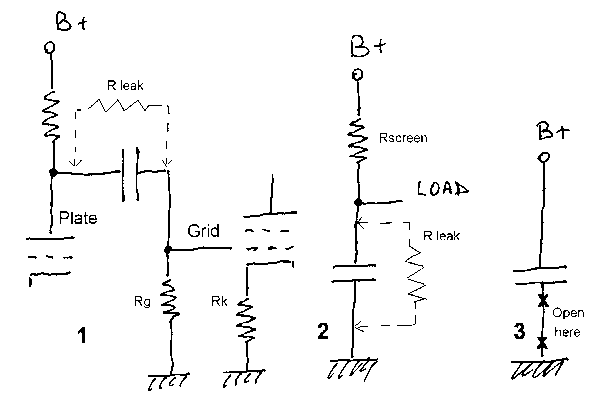
In the circuit 1 the capacitor is used to remove the DC voltage component from the signal applied to the grid of the second stage. Here the capacitor leakage is represented as a resistor, R-leak, in parallel with the capacitor. The higher the leakage current, the lower the value of R-leak. The circuit comprising R-leak and the grid resistor of the following stage is a voltage divider for the DC voltage available on the plate of the triode. Now we can evaluate if the capacitor must be replaced, simply measuring the voltage across the grid resistor. If we had removed both tubes from their sockets before this test, we are stressing the capacitor with the full B+ voltage, while eliminating spurious readings due to possible grid currents in gassy tubes. Any positive voltage value across Rg counteracts the negative bias specified for the power amplifier and usually generated across the cathode resistor Rk. Well, if the absolute voltage measured across Rg is in the order of one tenth of the nominal bias voltage or more, the capacitor must be replaced regardless of its leakage. On the contrary, if the measured voltage is low, say few millivolts, no need to replace the capacitor. This can be the case of a low ohmic value for Rg, say 10 to 47 kohms.
The circuit 2 shows a filter capacitor to chassis, as in the case of the screen grid supply of many tubes. Here normal voltage drop is caused by the load, as the screen grid current. Any leakage current of the capacitor increases the voltage drop across the upper limiting resistor. But the capacitor must be replaced only when this drop becomes excessive. A simple way to evaluate the proper insulation of the capacitor is to remove the tube from its socket and measure the voltage drop across Rscreen, or VB+ minus Vload. If this drop is in the order of a couple of volts or less, no need to replace the capacitor.
The third circuit shows a filter capacitor sometimes found between B+ and ground as interference suppressor. Here even a current in the order of one milliamps, equivalent to insulation resistance well under 1 megohm, does not affect the operation of the circuit and can only be dangerous for possible thermal effects. Anyway the insulation can be readily measured placing a resistor of, say, 100 kohms between the capacitor and the chassis ground and reading the voltage drop across it. The leakage current in the capacitor can be then easily calculated.
Regards, Emilio
To thank the Author because you find the post helpful or well done.
Clarification
Your Fig1 is very clear.
However a Battery valve set would want to be powered with the filament battery disconnected as the 90V HT is needed to "show up" the capacitor breakdown. If the heater was connected the audio output transformer might be damaged before the voltage can be meausred.
Also in some situations the capacitor might not be easily accessible to the multimeter when the set is powered normally.
I too believe there is no need to automatically replace every component of a certain kind. I do only replace parts only actually faulty.
I think though with non-electrolytic capacitors we must differentiate between leakage and actual breakdown. On my set none of the replaced capacitor had measurable leakage (all > 47 M Ohm) without HT, but all about 2M ohm with approximately 50V DC. At 300V DC, the 350V capacitors behaving like < 1M Ohms.
My cheap "tool" sugguestion is for those situations where it's not safe or easy to test the voltage drop across the capacitor with a Multimeter (Which often has an upper limit of 10M or 47M for measuring resistance, which may suggest the capacitor is fine when it isn't). Note also that many cheap DMMs are only 1M Ohm and the better 10M Ohm meters on voltage rage while suitable in many situations may not be high enough impedance for some circuits to decide if there is a problem with capacitor or you are seeing current through the DMM (470k Grid resistor vs 4.7M Grid resistor). If in doubt test the capacitor at the working voltage, not the low voltage of cheap meter.
Expert examination of a circuit (if available) will suggest what is acceptable leakage. But none of my "stock" non-electrolytic capacitors (even ones only rated 50V) light the neon at all once the capacitor is charged.
To thank the Author because you find the post helpful or well done.
Just an arbitrary value
47 Mohms insulation resistance for a capacitor is just an arbitrary value. I have many unused military metal-can paper capacitors, several hermetic too, and I read as low as about 10 Mohms for some high-capacitance units.
Anyway, assuming that in the above circuit (1) B+ is 250 volts, with 47 Mohms insulation resistance, you have over than 6 microamps leakage current. This current flows in the grid resistor of the following stage, causing a voltage drop of some 3 volts, if the grid resistor is 470 kohms, and over than 6 volts for a 1 Mohms resistor. Due to the said drop, the negative grid bias voltage of the following stage is then moved abnormally to zero or even to positive values. The grid bias voltage of a power pentode as the EL84 is in the order of -7 volts. Probably the power stage will then be browned within few hours. And all the smoke after your test gear had just returned a 'GOOD' reading!
And I repeat, in other circuits even leaky capacitors, 5 Mohms or less, can perform well and do not need to be replaced. A 'GO/NO-GO' tester is useless if not harmful, unless one is able to set either the acceptance or the reject limits on a case by case basis.
Of course anybody is free of following his ways, even the wrong ones. It is common practice to replace every caps, high frequency too, and then throw anything away. I know people that removed the entire chassis from a wooden cabinet and installed a CD reader inside. These are just other ways to restore an old radio. I wrote these notes to show a correct approach to the many peoples that never saw vacuum tubes and aim to use their head to do a good job in restoring their old sets.
To thank the Author because you find the post helpful or well done.
Insulation tester

Dear Mr Ciardiello:
It is a wonderful article. I visited the insulation tester site. Can you please suggest which insulation tester is needed to work for post war German tube radios.
Thank you
M Khan
To thank the Author because you find the post helpful or well done.
Megohmeters
Dear Mr. Khan,
as I explained above, I prefer to evaluate the insulation of a capacitor by its influence on the surrounding circuit. Often the simple voltage reading across the resistor usually found in series with the suspected capacitor, made with a high-impedance voltmeter, gives the ultimate yet more reliable answer. Anyway I found an insulation meter very useful either to check the insulation of other components, as the power transformer or the line filter capacitors, and to check the replacement capacitor: very often indeed I found NOS capacitors, even hermetic military ones, about as leaky as the capacitor I was going to replace.
The accuracy of the meter is not important. Two features should be preferred. The first one is the availability of more than one test voltage, to check even low voltage components. Two voltages, 50 and 500V, cover almost all of the needs. The second high recommended feature is the discharge of the capacitor at the end of the test, to prevent unpleasant shocks.
The best megohmeter I ever handled is the Gen Rad 1862: about ten years ago I lent mine to a friend and I lost meter and friend. Anyway occasionally some of these meters can be seen on ebay.
Very appreciated are the insulation meters from AVO Megger. Unfortunately they can be very expensive and, as I said, accuracy is not necessary.
Here, at MultimeterWareHouse, are listed some affordable insulation meters, good enough for the purpose.
Emilio
To thank the Author because you find the post helpful or well done.
Megger
Mr. Ciardiello:
Thanks a bunch my friend. You don't now how much a beginer like me appreciates the knowledge we gain from a pro like you.
Regards
M Khan
To thank the Author because you find the post helpful or well done.
Replacing old capacitors
Count of Thanks: 72
Mr Clardiello,
I learned a lot from your article about old capacitors. It is an excellent piece of information.
Thank you,
Ho
To thank the Author because you find the post helpful or well done.
Replacing old capacitors
I believe it a must to replace capacitor whether found good or leaky when in the primary of the out put transformer from the plate of the output tube to ground, as in some Saba radios. If this capacitor goes faulty there is a possibility of damaging the output (speaker) transformer. Kenneth Elwin.
To thank the Author because you find the post helpful or well done.
Misconception
Dear Kenneth,
your advice derives from the common misconception that a new component is anyway more reliable than an old one: this is completely wrong!
A new component usually has higher failure probability than the old one during its first hours of life. When considering similar components, one new and the second aged, failure rate of the new one stabilizes to the levels of the old one after about 3000 hours. When talking of reliable military components, you should remember that their associated infant mortality is someway limited running a burn-in or, for the Arrhenius law, an accelerated life cycle at high temperature. And these components were built in controlled environment, according to reliable and traceable processes.
Here we refer to commercial components, made somewhere in the Far East, unknown processes and handling, unknown materials The probability of an anticipated failure is quite high. More, when you have enough energy transfer through the dielectric, as in the case of the capacitor across the output transformer, you MUST select a suitable dielectric. A polyester film capacitor could swell and explode if used in such an application. Do you know how to specify the proper dielectric for each circuit? And, provided that you know which dielectric is best suited for a given application, do you know where to find the proper replacement capacitor? Are you capable of properly handling the new capacitor during the soldering, to prevent mechanical and thermal stresses? Are you capable of safely ageing the new capacitor, to prevent infant mortality failures?
As you can see, the replacement of a good capacitor with a new one is useless at all, if performed by a highly experienced technician. It even becomes crazy and harmful when attempted by an inexperienced person. If you fear possible future damages to the output transformer, just add a simple fuse to the B+ line.
Kind regards
To thank the Author because you find the post helpful or well done.
Capacitor replacement.
I like to clean up my old radios, mostley German and leave in the old capacitors after testing and replacing them only if showing leakage, from my experence I have had two near desarsters in leaving what I thought was good and original capacitor on the output transformers in a Saba radio (Most of my radios are Saba's). You are quite correct chosing a suitable capacitor is very important, in particular this one. It is noted that these old capacitors do very well for thier age, which shows the quality of the time they were made. Note. Saba radios seem to have the large capacito problem than other brands. I have a stock of old new capacitor I use if possible.You comments are very proffessional.
To thank the Author because you find the post helpful or well done.
If isn't broken don't fix it
The most critical place isn't on the transformer Anode to HT (or sometimes Anode to chassis/0V) but the grid coupling capacitor. Again in line with what Emilio Ciardiello says, never replace undamaged working parts. The Grid coupling has maybe 200V from previous anode and the "grid leak" resistor may be 2 M Ohms, so 1uA would reduce the grid - cathode voltage by 2V and increase anode current. But the rise in Cathode current reduces the effect as that increases the grid-cathode voltage. So the change is less than 2V (negative feedback).
If that capacitor isn't leaky at 200V I leave it alone.
The real tolerances for the radio working well are also often more than the tolerance of the component, so a component or two maybe 20% out doesn't matter. Exceptions are cathode bias resistors and oscillator capacitors. The exact value of a "grid" resistor, coupling capacitor or decoupling capacitor rarely matters.
In this case "If isn't broken don't fix it" is really true. Most people are more likely to create faults.
To thank the Author because you find the post helpful or well done.
Something of notable mention

I just finished bringing a late 1930's Firestone (model number S-7427-8) back into working condition. This one has been a "tough dog", or a rather a difficult radio to fix. At the start, i replaced all of the usual suspect capacitors, the wax covered film and foil units with newer dipped ones, plus replacing all of the electrolytics with their new modern counterparts. Performance was terrible, even after doing a rough alignment, with it further degrading after the set was on for a while. Tube subtitution didn't change anything, even though all of the original tubes were in fantastic shape. Doublechecking my work didn't reveal anything out of place.
I knew there had to be a component failing under load, and after doing some research elsewhere on the internet, i read that the old "Aerovox" mica caps were getting old enough that failures are starting to be noticed. On a hunch i decided to do one section at a time starting with the second IF, replacing the mica-molds with the newer siver mica dipped capacitors. A MASSIVE improvement was noted after replacing C14 ( 150pF ) and C15 ( 250pF) located on the secondary side of the second IF transformer. At this point i decided to replace all of the "Aerovox" mica-molds in the remaining sections ( first IF and mixer sections). The IF section aligned very quickly and it's gain was rather astounding compared to what it was previously. I'm pleased to report that the radio is working properly now!
As a precaution from now on, i am going to replace the mica-molds in my future restorations. I spent two months on this problem.
As a word of caution, some of these cap's are located within the IF can itself, and it's very easy to break the delicate wiring inside of the transformer. Take your time and work under good lighting.....
To thank the Author because you find the post helpful or well done.