Rustika lightbulb FM measurements
Rustika lightbulb FM measurements

Dear RMORG friends and, in particular, a special salutation to Prof. Dr.-Ing Dietmar Rudolph.
Dr. Rudolph very kindly gave me one, and later, several more of his Rustika Light bulbs that produce spontaneous FM band RF oscillations.
My interest in this light bulb came from an earlier thread that Dr Rudolph sent me, where the origin of these RF oscillations was explored. I used Google Translate to read the thread in English. The translation works for public threads, but not for members-only threads.
The basic nature of the oscillations was settled in the earlier thread.
Hard vacuum vs gas light bulbs:
The Rustika bulb has a hard vaccum, as has been the case with filamentary tungsten bulbs since the early part of the 20th century. In 1913, Irving Langmuir invented the modern light bulb design that uses a doulbe helix of tungsten and can be immersed in almost one atmosphere of nitrogen to dramatically reduce sublimation of the tungsten filament. The nitrogen atmosphere is not used with straight filamentary bulbs because the heat loss of a straight filament makes the bulb too inneficient. So filamentary bulbs in hard vacuum are limited to lower power ratings, where the filament is run cool enough such that tungsten sublimation is reduced to provide adequate bulb life. The Rustika with it's low temperture warm color glow is one of these bulbs.
Hollman explains filamentary anode oscillations:
As pointed out by Dr. Dietmar in the earlier thread, the physics of the bulb oscillations were first explained by Hans Hollmann in 1935. The excerpt from Hollmann is here in German and in English (The english translation needs improvement, please send suggestions).
The oscillations in this bulb are of the same nature of oscillations that were observed in a bulb with a filamentary cathode and a filamentary cold anode.
My current understanding has been iluminated by Hollmann's explanation of the filamentary tube oscillations as a retarding E-field type of oscillation that is usually used to explain Barkhausen oscillations and Klystron oscillations.
In the case of this bulb, the anode filaments behave like the grid of a triode barkhausen oscillator, but there is no plate to reflect the electrons. A balistic sling-shot effect slings the electrons around the filamentary anode in both directions around the anode filament simultaneously. Magnetics is not essencial to the effect, as can be seen in the first example shown in the book that has a cold filamentary Anode with zero DC current.
Note that the absense of the actual retarting plate of the triode Barkhausen oscillator type, helps orbital electrons moving in the diode filamentary tube, maintain much higher coherence than Ed Lyon has seen in his measurements of triode Barkhausen oscillations. My experiments show that it is easy to obtain better than 40dB of SNR in the Rustika oscillations. (Ed Lyon is not a member of RMORG, but was engaged in private email discussions of this topic. Ed published an article in the Mid Atlantic Antique Radio Club -MAARC to share some of our findings)
Electrons dance in a two cloud duet:
After studying Hollmann's explanation and reflecting on my measurement results, I see the electron behavior as follows:
1-The cathode supplies an omnidirectional electron cloud.
2-The anode attracts this cloud, but because of the filamentary nature of the anode, most electrons miss the anode.
3-Electrons that happen to approach the anode at the right angle will undergo a slingshot trajectory, like a rocket going around the moon. In this case the attraction is electrostatic, and not gravity.
4-Some electrons will go around the anode in a clockwise direction, while others will go in a counter-clockwise direction.
5-These electrons traveling in opposite directions of similar orbits wil interact with each other.
6-It is helpful to think of the counter-rotating electrons as counter-rotating clouds: As each of these clouds leaves the vicinity of the cathode, they gain speed from the anode pull.
7-As each of the clouds passes the anode on the right and on the left, the same anode pull, will now retard the speed of the two clouds, as they travel toward each other on the far side of the node.
8-When the two clouds approach each other on the far side of the anode, they repel each other, causing a further slow-down.
9-When the clouds merge temporarily at the far side of the anode, they form momentarily a more dispersed cloud because of mutual repulsion between electrons.
10-The mass inertia of the electrons makes the two clouds re-emerge from the temporary single cloud, as they return from the far side of the anode.
11- As inertia and the orbital attraction of the anode direct the two clouds toward the cathode, they become denser again because of the cathode repulsion.
12-The two clouds merge again in the space between cathode and anode, and can restart the orbital process with newly emitted electrons joining in to make up for electron loss along the way.
RF Radiation:
When we see RF emanating from the bulb, it is the periodic merge into one cloud, then two clouds, then one again, repetitivelly, that radiates the energy. Different ammounts of energy are stored in one merged cloud than two, so energy variations are seen as RF. The action of merging into electron clouds and then dispersing, is commonly described in transit time tube literature as electron bunching. Transit time tubes include Klystrons.
No L and no C:
Measurements that I will share below show that there are no inductive or capacitive storage elements involved in these oscillations. There are no resonant cavities that store and release energy into the electron bunching that is seen in a klystron. The clearest proof that no fixed mechanical storage devices such as capacitors, inductors, delay lines or cavities, are involved is the fact that the frequency of oscillation is directly proportional to the anode voltage, in a very smooth monotonic fashion. Please see forumdata/users/4942/file/Rustika_Frequency_vs_Voltage.pdf
These plots show that frequency of oscillation is 60MHz with 180VDC and 105MHz with 240VDC. Higher voltage also increases the intensity of the oscillations from 35mVp-p at 60MHz/180VDC to 140mVp-p at 80MHz/240VDC.
Pure Sines:
The oscillations can be very pure. The rumble/noise that was seen in earlier spectral measurements was caused by the effect of stray electrostatic fields at 60Hz/50Hz line frequency and by mechanical vibrations of the very thing filaments. I found that shielding the bulb with a metal mesh eliminated electrostatic field interference, and placing the bulb in the horizontal position stabilized the mechanical vibrations of the filaments.

The oscilloscope is set in dual time base mode, with the B time base set for 10ns/div, and the A time base set for 500ns/div. When sweep is triggered on the left, there is no apparent jitter on the first cycle then, after the delay, the jitter accumulates and shows the jitter in more detail.
Oscilloscopes show externally induced jitter:
These scope photos show a higher level of jitter with the bulb in a shielded can, but supported vertically, so the filaments could vibrate mechanically. Each of the six shots shows the same wave with increasing delay from the trigger moment to show accumulated jitter over 5us. The upper trace, where the jitter is seen, is 100ns/div. The lower trace is 500ns/div. This method offers an alternative to the spectrum analyser to evaluate jitter.

This same wave produces this spectral plot, where the low frequency mechanical vibrations of the vertically mounted bulb are apparent around the fundamental.

You can see data from this spectrum analiser in more detail here.
The setup for these two results is shown here:
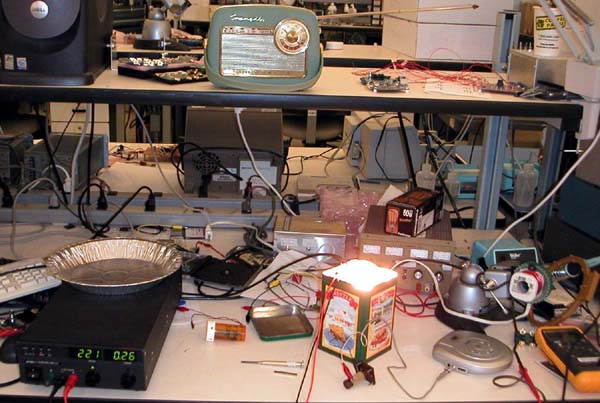
The bulb was shielded but still exhibited mechanical vibrations that could be heard on the Nordmende Transita radio nearby.
Electrostatic shielding and magnetic immunity:
Electrostatic attraction and repulsion lie at the heart of the these oscillations. That is why the shield was so effective. Magnetic fields, on the other hand, have a weak effect. When I applied a magnetic field of a few ampere turns with a hand made solenoid over the bulb, I could only slow down and reduce the amplitude of the oscillations. I tried various directions of the magnetic field, but none helped. So I draw the conclusion that the DC magnetic field is not an essential part of the oscillations, and only serves to disrupt the oscillatioins.
Rustika bulb broadcasts HIFI in FM band:
You see a CD player in the setup above, and one in this setup below:
![]()
I used the CD player to modulate the shield voltage with about 200mV p-p to produce 100kHz of FM modulation on the bulb frequency. The small ceramic cap still gounds the shield at RF frequencies. This illustrates how tremendous is the sensitivity of the bulb to external electric fields.
Tracking FM radio:
The radio I hold in the foreground is the guts from a very cheap scanning FM radio that you find in discount stores. It uses a button to scan for FM stations, and locks on to them with a phase-lock-loop action. This tracking type of tuning is ideal to hear the FM modulated transmission, because the carrier frequency drifts as the bulb warms up.
Horizontal position for bulb:
With the bulb in the horizontal position, and the electric shield the FM transmission was very clean. I think the music I heard was so clean that the SNR was no worse than 60dB, thus proving that very coherent sinewave generation is possible.
Filament temperature:
One effect that may be of concern for those originally pondering the nature of the oscillations is the filament temperature. I made some measurements of DC current as a function of DC voltage, and correlated them to the well known temperature/resistivity curve of Tungsten in Rustika_Filament_Temperature.pdf . The filament temperature is 3200K with 240VDC and 3000K with 180VDC.
E-field map:
We have established that there is extreme sensitivity to external electric fields. I set about mapping the sensitivity to electric fields over the surface of the bulb. I used the end of a BNC cable as the probe, while O measured the amount of FM deviation. The pin in the BNC connector has a very small area, so I drove the cable with 100Vp-p at 2kHz from my HP200AB Wein Bridge Sinewave oscillator.

The following spot shows the location for high FM modulation sensitivity. It is located a about 60o away from the anode terminal. The anode end of the fillament is below the cathode end in this picture.

A complete mapping of the surface of the bulb showed that the peak sensitivity to FM modulation occurs approximatelly opposite the cathode and anode terminals. In any case, the highest sensitivity is always observed near the equator of the bulb. A 10 to 1 sensitivity variation was observed along the equator.

The sharpness of the high sensitivity location suggests that the oscillatory orbits around the the anode filaments may be toroidally shapped. A cylindrically bounded sheet beam is not likely with this sensitivity profile. Additional views of this data are available in Rustika_FM_map_2-4.pdf.
An additional file compares sensitivity along the equator line for the two frequencies 86MHz and 100MHz in Rustika_FM_2_FREQUENCIES.pdf.
Multi segment Rustika vs. Hollmann's single filamentary anode:
I have not addressed the obvious difference between the oscillations in a two electrode tube as described by Hollmann, and the multi-segment bulb we have been examining. I welcome analysis of my results and some imagination on the part of readers to contribute a connection. In the mean time, I have simulated individual electron trajectories in QuickField electrostatic simulator. Simulating single electron paths is fundamentally different from electron cloud paths with interacting electrons, but these simulations may serve to seed the imagination of readers.
Static Electric Field Simulations:
The following plot shows the electric field around a grounded cathode and a filamentary anode, seen in cross section. the circular periphery is grounded as a shield. The pink line shows possible electron paths.

The following plot shows the fields around the Rustika bulb with it's 20 segments. The periphery is a grounded shield. The pink lines show a possible electron trajectory. In this case, the electron was dropped near the cathode with a particular initial velocity and direction.

QuickField offers a demo version that can simulated electron trajectories for simulations that have a previously calculated simulation mesh in licensed version of their product. If you like I can send you the solved files. Email your request to K2W at PhilbrickArchive dot ORG.
Oscillations in single filament light bulbs:
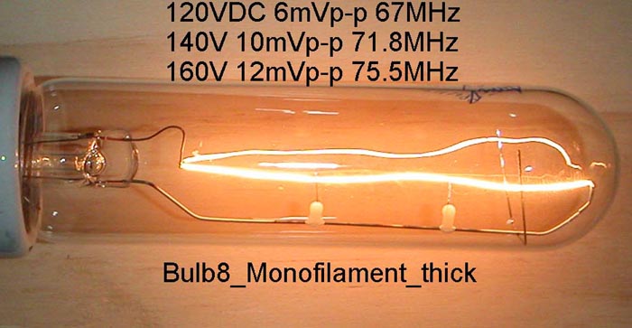
While thinking about the original Hollmann tube with two electrodes I wondered if such a structure could be found in modern constructions. I found that long light bulbs that are usually sold for small fish tanks or furniture ilumination can produce weak oscillations with just two electrodes. The following two bulbs showed weak oscillations. The sensitive part of the oscillations was near the anode end of the filament at the base of the bulb.

I bought approximatelly ten of these monofilament bulbs, and these two are the only two that oscillated. When I was shopping for bulbs, I looked for bulbs that had a particular close placement of the cathode filament to the cold anode rod near the base of the tube. The threaded part of the socket is usually connected to the metal rod that will serve as the anode, and the filament is tied to the button end of the socket.
Multi-segment bulb survey:
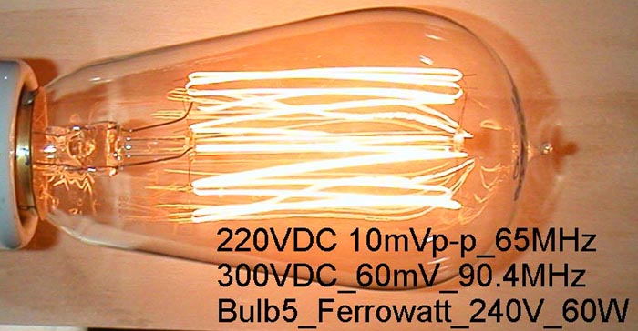
Now a survey or other multi segment bulbs, starting with the original Rustika sent to me by Dr. Rudolph, and a few more Rustikas also sent by Dr. Dietmar, along with a few others I acquired. Not all multi-segment bulbs oscillate, but they are more likely to oscillate than the mono-filament bulbs shown above.

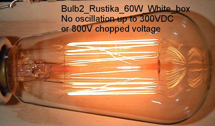


Bulb2 in this series never oscillated, despite the fact that it is constructed similarly to the other Rustika bulbs. Perhaps the difference lies in the wider segment spacings.
High Voltage supply chopper up to 800V peak:
I built a supply voltage chopper to apply higher voltages up to 800V to the bulbs, while keeping the total power and filmament temperature fairly constant with a low duty cycle. The schematic for the the chopper is in HV_CHOPPER.gif
The results from the chopper action were surprising. I found that it may take several miliseconds for oscillations to start, after 800V is applied to the anode side of the filament.
.JPG)
The following detail shows onset of oscillations with a 800V pulsed supply. The pulse frequency is 100Hz, and the pulse width is 1ms. The bulb is a 60W rustika running at 60W average power.
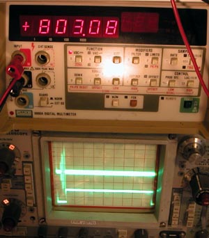
I repeated this chopped high voltage experiment with several bulbs and supply voltages, and found that bulbs that oscillated with a DC voltage of 240VDC did not oscillate with some of the higher chopped voltages because there was not enough time to start oscillations.
One factor to consider that may delay the onset of oscillations is charge accumulation in the inside walls of the bulbs. This charge would have a repelling function, and would have a strong effect on oscillations.
Oscillating eye tubes?
One last bulb type I have thought may oscillate is the common eye tube. Most eye tubes have a filamentary deflection anode. Perhaps a set of bias conditions could be found that produces coherent oscillations as Hollman described. It would be nice to hear if someone got an eye tube to oscillate.
As I close this submission, I send my warm appreciation to Prof. Dr.-Ing Dietmar Rudolph.
Comments invited, especially from participants in the earlier thread discussions.
-Joe Sousa
To thank the Author because you find the post helpful or well done.
Congratulations

Congratulations Joe,
this is an excellent investigation and a very informative report.
Best regards,
Dietmar
To thank the Author because you find the post helpful or well done.
Dear Dr. Rudolph, Thank you for your kind words.
I look forward to feedback from other readers.
Someone with a strong Physics background could do a sanity check on the oscillation model put forth by Hollmann as I interpreted it, with dancing dual electron clouds. Perhaps planetary motion, supplemented with statistics could describe the oscillatory behaviour mathematically.
Regards,
-Joe
To thank the Author because you find the post helpful or well done.
Hollman explains filamentary anode oscillations
Fellow Radiophiles:
My understanding of German has improved substantially since I started taking German language classes at the Goethe Institut in Boston. The teaching quality is excellent. I used my improved skill to attempt a better translation of the explanation given in 1935 by Hans Hollman for the behaviour of VHF oscillations around filamentary anodes.
The explanation was extracted from pages 150-153 of "Ultrakurze Wellen" – Vol 1 as originally pointed out by Dr. Dietmar Rudolph.
The pdf attachment is arranged in two parallel columns. The left column contains the original German text as extracted with OCR from my copy of the book, and the right column has the English translation. The original German text was corrected for OCR errors and the English text was first obtained with the Google translator to get unfamiliar vocabulary. Then I edited the somewhat mangled translated English sentence structure. Sentence structure is the greatest weakness of Google Translations from German to English. Finally, Dr. Rudolph made corrections to the English text to ensure that it reflected the original meaning. Dr. Rudolph also spotted and corrected an original drafting error at figure 193.
This clarified translation shed new light in my understanding of the space charge oscillations around the filamentary anode.
For example, the illustrations of fig 196 now suggests to me a standing wave pattern that stretches over two opposing orbital paths around the filamentary anode. This standing wave pattern radiates at one frequency. These paths overlap and should interact. However, one of the more interesting new understandings is that it is possible to alter the standing wave pattern of one orbital direction with respect to the other orbital direction with the application of a weak magnetic field of a couple of Gauss. The text reports a case where a 174MHz oscillation (wave length=172cm) split into two distinct oscillations 9MHz apart. This suggests that the head-on collision of the two space charges orbiting from the left and from the right of the filamentary anode at the far side of the anode, is not necessary for coherent oscillation.
Best regards,
-Joe
Attachments:To thank the Author because you find the post helpful or well done.
Reducing the Cathode-Anode gap
Fellow Radiophiles:
The measurements in this thread show that it is helps to have a smaller gap from the Cathode end of the filament to the cold Anode rod to obtain oscillations. One simple trick to bring the filamentary cathode closer to the Anode rod is to strech the filament while it is hot under AC power by vibrating it under the influence of a strong magnet.

Note how the filament vibrates from the interaction between the AC 60Hz that is generated by the 1/3A AC current flowing through the filament and the fixed field of the Magnet.
Some experimentation is required to avoid breaking the filament. One convenient way to control the ammount of vibration is to drive the bulb with a variable source of AC voltage, like a Variac.
The portion of the filament that needs streching is at the bottom of the bulb where the greatest DC electric field can be generated when a DC voltage is applied for the generation of a clean VHF frequency.

Note how the bottom part of the filament is nearly twice as close to the anode rod as before.
The bulb must be oriented horizontally with the anode rod at the bottom for the smallest gap from the cathodic filament to the anode rod.
This mechanical suspension of the filament is very microphonic, so you need a very steady bulb. support.
If you manage to get oscillations into the FM band, you could modulate them with audio from a CD player driving an RF-grounded metal mesh shield as shown above for the Rustika bulb. Copper tape or simply wrapped wire may also work as the external electrode to drive the audio modulation.
Remember that the FM radios that work best often are the very inexpensive type shown above with a scanning button that can follow the drifting frequency from the bulb automatically.
It would be great to hear about any sucessful FM radio transmissions emanating from these light-bulbs.
I live in the USA, so my choice of bulbs is limitied to 120V. If this format of bulb can be found in countries with 240V power, it may be easier to create the oscillations with the higher voltage.
Best regards,
-Joe
To thank the Author because you find the post helpful or well done.