Substituting the rare two-cathode 6X6
Substituting the rare two-cathode 6X6

A number of Canadian De Forest and Rogers-Majestic radios from 1937 to 1940 were fitted with the improved two-cathode version of the 6X6 magic eye tube, to create two wider shadow angles, which improves the utility of this eye tube considerably, as compared to the then usual eye tubes with only a single and narrow shadow angle as the 6E5.
Unfortunately only very few of these two-cathode 6X6's have survived. One can substitute them by a normal single-shadow angle 6X6 version or by a British Y63 or Vi103, but the unique feature of the two-cathode 6X6 is lost then.
However, there is a chance to achieve virtually the same two wide-shadow angles display of the two-cathode 6X6 by substituting it by a 6AF6G and an additionally control triode, such as the 6L5, 6J5 or 6C5.

The diagram above shows how the tubes 6AF6 and 6L5 can substitute the 6X6 in many Roberts-Majestic radios.
An input voltage of -14...15 V at the triode grid results in full output of the 6AF6's shadow angles, which can easily be achieved by receiving stronger stations. The input voltage divider resistors R18 and R19 may be altered for proper indication, e.g. by matching them to full output by the strongest incoming station. It may be advantageous to replace R18 and R19 by a 1 MegOhm trimpot for easier adjustment.
If the radio has two 2X3's as rectifiers, then there is a good opportunity to accommodate the 6L5 control triode. One can remove these 2X3's and replace them by one 5Y3G/GT, while the one spare socket will then be used for the 6L5.

Both of these pictures show a comparison of the true two-cathode 6X6 (top) to the 6AF6 (below), controlled by a 6L5. That clearly proves the 6AF6 as a fully equivalent substitute of the 6X6.

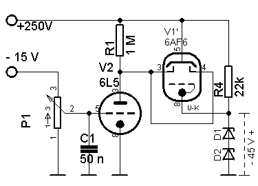
The diagram above shows the test circuit used to simulate the conditions of the Roberts-Majestic radios using the 6X6.

This animated picture shows a sweep from 0 V to -15 V control voltage at the grid of the 6L5 control triode.
Getting out even more of the 6AF6 !
If you use the 6AF6 anyway, why not trying to get the most out of it ?
There is the possibility to drive both indicating sections successively rather then drive them in parallel as usual, which gives a much better resolution of the indication range.
The indication range is extended over both sections successively. Weak signals are only displayed on the first sector. The second sector displays the stronger signals and starts not before the first sector is fully closed.

See more under :
(Proof read by J. Sousa. 12-17-2011)
To thank the Author because you find the post helpful or well done.