radiomuseum.org
Please click your language flag. Bitte Sprachflagge klicken.

6AF6G

Information - Help 
ID = 3245
       
Country:
United States of America (USA)
Brand:
Developer: RCA (RCA Victor Co. Inc.); New York (NY) 
Tube type:  Mag. Eye, 2 ranges, 2 shadow angles   Indication 
Identical to 6AF6G = CV847 = 6AF6-G = 6AF6-GT = 6AF6
Similar Tubes
Other characteristic (electr. data):
  6AD6G
First Source (s)
07.Jun.1938 : Electron Tube Registration List

Base Octal (Int.Octal, IO) K8A, USA 1935 (Codex=U)
Was used by Radio/TV-reception etc.
Filament Vf 6.3 Volts / If 0.15 Ampere / Indirect / Specified voltage AND current AC/DC
Description

Dual independent shadows, whitout integrated amplifier triode, to be controlled by a 6AE6G.
First intoduced in 1938 by RCA as extremely small size G envelope, 2-5/16 inch, possible with the elimination of the conventional stem.

 
Text in other languages (may differ)
Tube prices 2 Tube prices (visible for members only)
Information source Essential Characteristics, GE 1973   
-- Original prospect or advert   Electronics, August 1938

6af6g.png
6AF6G: RCA Manual RC-14
Heinz Höger

6af6g_so.png 6AF6G: ARRL Handbook 1972
Anonymous 10 Collector

More ...

Just Qvigstad
6af6g_rca_data_01.png
6AF6G: original data sheet
Bernd Staginnus

More ...
Usage in Models 2= 1938? ; 22= 1938 ; 5= 1939?? ; 12= 1939? ; 34= 1939 ; 4= 1940?? ; 7= 1940? ; 23= 1940 ; 2= 1941?? ; 1= 1941? ; 14= 1941 ; 1= 1942?? ; 1= 1946 ; 1= 1947? ; 2= 1952?? ; 1= 1952 ; 1= 1954 ; 1= 1956 ; 1= 1957? ; 4= 1958?

Quantity of Models at Radiomuseum.org with this tube (valve, valves, valvola, valvole, válvula, lampe):139

Collection of

 
6af6_01rm400s.jpg

6AF6G
 

Forum contributions about this tube
6AF6G
Threads: 2 | Posts: 4
Hits: 3385     Replies: 0
  Optimale Ausnutzung der 6AF6G
Jacob Roschy
17.Sep.11
 
  1

 Optimale Ausnutzung der 6AF6G

Um bei Magischen Augen einen möglichst großen Signalbereich optisch gut darstellen zu können, wurden Röhren mit zwei Anzeigebereichen geschaffen, teilweise mit 2 Leuchtwinkeln (EM4, EM34) oder mit 4 Leuchtwinkeln (EM11, EM35, frühere 6AF7).

Die beiden Anzeigebereiche haben eine unterschiedliche Empfindlichkeit, so dass das der eine Bereich schon bei einer eher kleinen Spannung, entsprechend Empfangssignalen mittlerer Stärke, schon Vollausschlag erreicht, während der zweite Bereich erst bei sehr starken Signalen Vollausschlag erreicht.

Als Nachteile dieser Anzeigeröhren wäre anzumerken:

  • der Schattenwinkel ist maximal 90°, dadurch bleibt ein großer Teil des Leuchtschirms für die eigentliche Anzeige ungenutzt, da er nur konstant leuchtet. Dieser Mangel konnte bei den Röhren mit 4 Leuchtwinkeln teilweise ausgeglichen werden.

  • Der unempfindlichere Sektor bewegt sich von Beginn an parallel zum empfindlicheren Sektor mit, so dass schon ein wesentlicher Teil dieses Bereiches unnötig „verbraucht“ wird und sich nur noch ein verringerter Teil bewegt, wenn der empfindlichere Anzeigebereich schon voll ausgesteuert ist.
     

Das ideale Zweibereichs- Magische Auge, bei dem der Leuchtschirm voll zur Anzeige ausgenutzt wird, müsste folgende Eigenschaften haben:

  • ohne Empfangssignal zeigen beide Sektoren nichts an, d. h. der Leuchtschirm ist komplett dunkel oder man sieht nur noch zwei schmale leuchtende Streifen als Nullmarkierung.

  • Schwache Signale werden nur vom ersten Sektor angezeigt. Der zweite Sektor beginnt erst dann sich zu bewegen, wenn der erste Sektor Vollausschlag erreicht hat.

  • Der Bewegungsweg beider Sektoren ist jeweils 0...≤180°, so dass die gesamte Oberfläche des Leuchtschirms an der Anzeige beteiligt ist.


Eine Röhre mit diesen Eigenschaften gibt es nicht, aber mit einigem Aufwand kann man mit der amerikanischen 6AF6G diesen Forderungen schon relativ nahe kommen.

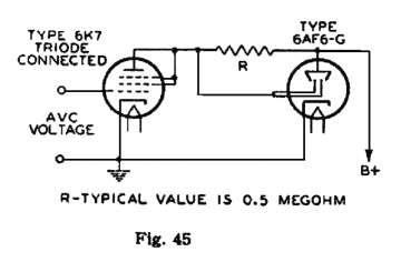
Diese 6AF6G hat zwei Schattenwinkel ähnlich der Röhren EM4 und EM34, besitzt aber kein eingebautes Verstärkersystem. Daher ist zwar immer eine weitere Röhre zur Ansteuerung erforderlich, aber man hat dadurch die völlige schaltungstechnische Freiheit. So kann man der 6AF6G Eigenschaften anzüchten, die mit anderen Magischen Augen nicht möglich sind.

Der Schattenwinkel von EM4 und EM34 ist maximal 90°, weil die positive Spannung der Steuerstege auch ohne Steuerspannung immer noch relativ hoch gegenüber der Katode des Leuchtsystems ist. Bei der 6AF6G lässt sich dieses Problem lösen, indem man deren Katode auf eine höhere Spannung gegenüber Masse (GND) anhebt, z. B. auf 75 V mittels einer Stabi- Röhre 0A3 oder 75C1.

Mit einer geeigneten Doppeltriode als Steuerröhre, z. B. eine 6C8G, ist es nun möglich, die Steuerstege stark negativ gegenüber der Katode zu steuern, wodurch beide Schattenwinkel sehr groß werden und nur noch ein schmaler leuchtender Streifen übrig bleibt. Der steuerbare, d. h. bewegliche Anteil des Leuchtschirms wird somit erheblich vergrößert.


Das Gitter G II der zweiten Triode der 6C8G erhält über einen 100 MΩ Widerstand einen positiven Vorstrom und ist über ein 5 MΩ Trimmpoti mit der Steuerspannung U-in verbunden, während das Gitter G I der ersten Triode direkt an der Steuerspannung U-in liegt.

Solange über das Poti P2 weniger Strom als über R3 fließt, bleibt die Spannung an diesem Gitter G II auf 0 V wegen dessen Diodenwirkung, obwohl sich die negative Steuerspannung erhöht. Erst ab dem Punkt, wo der Strom über P2 den Strom durch R3 erreicht, beginnt die Spannung negativ zu werden.

Die Spannung am zweiten Steuergitter G II wird also erst dann negativ, wenn die negative Spannung am ersten Steuergitter G I schon einen bestimmten Betrag überschritten hat.

Stellt man P2 so ein, dass die die negative Spannung am zweiten Steuergitter erst dann einsetzt, wenn das erste System der 6AF6G Vollausschlag erreicht hat, so erhält man einen fließenden Übergang von Leuchtwinkel 1 zu Leuchtwinkel 2 . Die gesamte Steuerspannung wird also nacheinander auf beide Leuchtwinkel verteilt.Die beiden Widerstände R5 und R6 bilden mit R1 und R2 jeweils Spannungsteiler, womit das Überlappen der Leuchtfelder verhindert wird.

In der Testschaltung betrug die Betriebsspannung +U-b = 272 V, die Spannung an der Katode der 6AF6G, U-k = 72 V, Leuchtschirmspannung U-l gegen Katode = 187 V. Der Spannungshub der 6C8G- Anoden verlief von 30...202 V (A I) , bzw. 17...202 V(A II).

Doppeltrioden mit µ = 30...40 und Innenwiderstand 20...30 kΩ, wie hier die 6C8G, sind als Steuerröhren besonders geeignet, so auch die 12AY7. Auch Doppeltrioden, die für Computer- Flip-Flop Schaltungen vorgesehen waren, sind vielversprechend, z. B. 1684, 2033, 6211, E90CC, usw.

Diese Röhren benötigen einerseits eine relativ geringe Steuerspannung für Vollausschlag und ziehen andererseits bei U-in = 0V die Anodenspannung tief genug herunter, so dass die Leuchtfelder der 6AF6G sehr schmal werden.

Röhren mit niederem µ, wie ECC82, 12AU7, 6AH7, ziehen die Anodenspannung noch weiter herunter ohne wesentlichen Nutzen, sie benötigen aber eine sehr hohe Steuerspannung zur Vollaussteuerung.

Röhren mit hohem µ, wie ECC83, 12AX7, 6SL7, benötigen zwar nur wenig Steuerspannung zur Vollaussteuerung, dafür ziehen sie die Anodenspannung nicht weit genug herunter bei U-in = 0V, so dass die Leuchtfelder nicht schmal genug werden.

Das Bild zeigt den Verlauf der beiden Sektoren der 6AF6G, angesteuert von einer 6C8G, während der Zuführung einer Steuerspannung U-in von 0...-15 V.

Man erkennt, dass in den beiden oberen Reihen nur eine Änderung im linken Sektor erfolgt, während in den beiden unteren Reihen sich nur noch der rechte Sektor ändert und der linken Sektor auf Vollausschlag verbleibt.

Im Anhang befinden sich 16 Einzelbilder des Anzeigeverlaufs. Bei entsprechend schnellem Durchscrollen lässt sich die Bewegung der Anzeige simulieren.

Unser Kollege Otmar Jung hatte die geniale Idee, ein animiertes Bild aus der Fotoserie anzufertigen, wofür Ihm herzlich gedankt sei. Wegen der begrenzten Dateigröße ist es leider etwas grießig geworden.

                     
Hier kann man jedoch deutlich erkennen, dass der Übergang von Sektor 1 nach Sektor 2 nicht optimal abgestimmt ist, da bei -7 V zu wenig passiert. Der verzögerte Einsatz von Sektor 2 beginnt leicht zu spät, so dass ein Teil der Spannungsänderung verschluckt wird. Dieser Fehler wurde schon erkannt und berichtigt, aber der Aufwand einer neuen Bilderserie wäre zu groß gewesen.


M. f. G. J. R.
 

Attachments

 
Hits: 10815     Replies: 2
The optimal use of the 6AF6G
Jacob Roschy
20.Oct.11
  1


In the late 1930s magic eye tubes were developed in Europe with two shadow angles, the EM4 and the EM34, or with four shadow angles, the EM11 and the early version of the 6AF7, which were controlled by integrated triode units with different plate sensitivities in order to handle a wide range of input voltages. The more sensitive shadow angle reaches full closing even at moderate input signals, while the less sensitive shadow angle closes only at strong signals.

However these two-range magic eye tubes have some disadvantages:

  • both shadow angles have a maximum opening of 90°, thus a big part of the fluorescent screen remains unused for the actual signal display, as it is lit without any change. This deficiency could be partially compensated by the tubes having 4 shadow angles.

  • The less sensitive section moves from the beginning in parallel with the more sensitive section, so that a substantial portion of the less sensitive section is wasted until the more sensitive section is at full scale. Only the remaining part of the display area is actually useful after the sensitive section is fully closed.

An ideal dual-range magic eye, in which the luminescent screen is completely used for the display, would have to have the following properties :

  • without input signal both sectors show no display, i.e. the fluorescent screen is completely dark with only two narrow light stripes as zero signal marks.
  • Weak signals are only displayed on the first sector. The second sector starts to display, after the first sector is fully closed.
  • Both sectors move from 0° to 180° so that the entire surface of the luminescent target is involved in the signal display.

Actually there is no tube available with these properties, but with some effort, one can come relatively close to these demands by using the 6AF6G eye tube.
The 6AF6 has two shadow angles similar to the European tubes EM4 and EM34, but it
contains no built-in amplifier units, which always makes a separate control tube necessary. Since this allows complete freedom of circuitry, the 6AF6 can be configured with display properties, which are not possible with any other magic eye tubes.

The shadow angle of the EM4 and the EM34 is 90° at maximum because,
even with zero input voltage, the positive voltage of the control rods is still relatively high with respect to the cathode. By using a 6AF6, this problem can be solved, if its cathode is biased at a higher voltage against ground (GND) up to +75 V with a voltage regulator tube 0A3 or 75C1.

With a proper double triode as control tube, such as a 6C8, it is now possible to pull the control rods to to a negative voltage against the cathode, so that both the shadow angles become
very wide and only a narrow strip is left lit with zero input signal.


A positive current bias is applied via a 100 MΩ resistor to the G II grid the of 6C8's second triode unit, while this G II grid is also connected to the control voltage U'in via a 5 MΩ trimpot. The G I grid of the first triode unit is directly connected to the control voltage U-in.

As long as less current flows through trimpot P2 than through resistor R3, the voltage at grid G II remains at 0 V while
the negative control voltage moves freely due to the grid diode clamping effect. The voltage at G II starts to become negative only at the point where the current through P2 equals the current through R3.

That means, the voltage at the second control grid G II will not become negative until the negative voltage at control grid G I has already exceeded a certain amount.

If trimpot P2 is adjusted so that the rise of the negative voltage on the second control grid just starts at the point, when the first section of the 6AF6G has reached full scale, a flying change of indication from shadow angle 1 to shadow angle 2 is obtained.

That way the entire range of control voltage is distributed successively to both indicating sections.

Resistors R5 and R6 form a voltage divider with R1 and R2 respectively, to prevent overlap of the luminous fields.

In the test circuit, the operating voltage + Ub was 272 V, the voltage Uk at the cathode of 6AF6 was 72 V, the luminous screen voltage Ul against cathode was 187 V. The voltage swing of the 6C8 plates went from 30 to 202 V (AI), and from 17 to 202 V (A II), by a control voltage swing from 0 to -15 V.

Double triodes with µ = 30 .. 40 and internal resistance of 20 to 30 kΩ, such as the 6C8 or the 12AY7, are particularly suitable as control tubes. Also some double triodes, which were developed for computer-flip-flop circuits are promising, e.g. 1684, 2033, 6211, E90CC, etc.

These tubes require a relatively low control voltage for full scale on both indicating sections and they also pull down the plate voltage low enough to get the luminous fields of the 6AF6 very narrow if control voltage is 0 V.

Low-µ tubes such as ECC82, 12AU7 or 6AH7, pulling down the plate voltage even further without any substantial benefit, but they require a rather high control voltage for full output.

If less control voltage is available, high-µ tubes such as ECC83, 12AX7 or 6SL7 may solve the problem. Since their internal resistant is also higher, the plate pull-up resistors R1 and R2 must be changed to 1 MΩ, the pull-down resistors R5 and R6 have to be removed. This way, a 6SL7 requires a control voltage of –7.5 V for full output of both 6AF6 sections, respectively -3.75 V for full output of the first section.


The image shows the course of the two sectors of the 6AF6, driven by a 6C8 as shown in the test circuit, while the control voltage U-in rises from 0 to -15 V.
On the 1
st and 2nd row from the top, only a change in the left-hand sector appears, whereas in the 3rd and 4th rows only a change in the right-hand sector appears, while the the left-hand sector remains at full-scale.

 Our fellow RM member Otmar Jung was so kind to make an animated image from the photo series, which is gratefully acknowledged to him.

However, it becomes obvious, that the transition from sector 1 to sector 2 is not optimally tuned, because at -7 V very little changes. The delayed start of sector 2 comes slightly too late, so that a portion of the voltage change is swallowed. This bug has already been detected and corrected, but the effort to make a new series of images would have been too much.

Best Regards, Jacob


Michael Watterson
20.Oct.11
  2

I presume the 6AD6, 6AF6 and 1629 are similar to 6AF6G and only vary in voltage or package?

Very interesting article. I had mentioned the dual control of 6AF6 here but with no example of how to use it. I've linked the paragraph to your article now.

Jacob Roschy
24.Oct.11
  3

Hello Michael,

the 6AD6 is indeed similar to the 6AF6(-G), but has a maximum target voltage of 150 V, while the 1629 is merely a 12.6 volt heater octal based version of the 6E5 with built-in driver triode and only one shadow angle, hence dissimilar to the 6AF6.

Thank you for setting a link to my article.

Best Regards, Jacob

 
6AF6G
End of forum contributions about this tube

You reach this tube or valve page from a search after clicking the "tubes" tab or by clicking a tube on a radio model page. You will find thousands of tubes or valves with interesting links. You even can look up radio models with a certain tube line up. [rmxtube-en]
  

Data Compliance More Information