Summary Russian Rod Pentodes
Summary Russian Rod Pentodes
Joe Sousa writes:
Russian Subminiature Tubes are constructed entirely differently from other subminiature tubes. The internal structure of conventional subminiature Tubes shown in figure 1 is easily recognized as a miniaturized version of the classic receiving tube structure, with a filamentary or a unipotential cathode, one or more thin wire ladders as grids, perhaps beam forming plates and, lastly, a classic anode plate.


Fig. 1 Conventional Subminiature tubes. SN891B-triode 5678-pentode
Fig. 2 Russian Subminiature Tubes. 1ZH29B 1P24B 1ZH18B. All pentodes.
Fig. 3 1ZH29B without glass envelope.
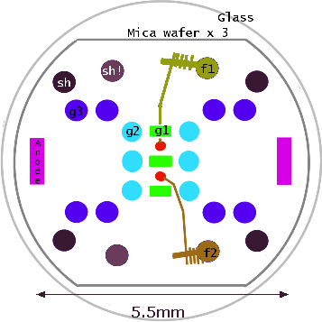
The Russian Subminiature Tube design shown in figure 2, is hardly recognizable as a triode, tetrode or pentode. The cathode is still a conventional filament, but the remaining elements are all constructed from similar gauge metal rods except for the control grid and anode which are both long flat plates . Figure 3 shows three micas; 2 at the ends and one in the center of the tube to hold the rods in place, with the central mica assuring low microphonics, and consistent element alignment.
The rods are arranged to control the electron path from the filament to the a diametrically opposed pair of flattened rods that serve as the anode. One of the anode rods is the widest visible left of center in Figure 3. The anode connection is always via the top wire.
There are only Pentodes in the "Rod" family as the characteristic is similar to a Pentode but construction is point source of electrons creating two beams which are each focused on one of the two anodes. The electrostatic lens is two sets of rods connected to 0V and HT. Thus inherently there are five external electrode connections: Filamentary Cathode, g1, g2, g3 and Anode. The g2 and g3 form a lens thus are not really the traditional Screen and Suppressor grids.

Cross-section diagram of the two beams and electrodes.
The cathode can't be indirectly heated. It has to be a filament to be a "point source" for the beams. There are no grid wires or meshes. On higher power tubes there may be two point sources and multiple rods for each electrode position.
There are three known variations:
 |
Normal small signal version Rods/Plates of the same colour are internally connected. The support rod for top of filament (always -ve end) is an additional electrostatic Shield/Screen. |
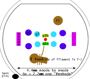 |
Mixer version The two g1 plates have separate connections. The action is opposite to a differential Amplifier. Common mode signals on g1a and g1b are amplified more than differential or balance signal. |
 |
Higher power version.has larger Anode plates and two filaments. 1j29b, 1p24b |
Most of the Rod pentodes work best at about 60V HT, with G2 at 45V and G3 at 0V. The g1 current can be under 100pA. Due to the unique construction at good HT you can have g1 up to +1V with less than 1uA on some models.
Triode type characteristics with either up to 25% more power or HT below 25V is possible by connecting g2 and Anode with g3 at 0V to maintain the lens. In Triode mode at less than about 5V to 18V HT depending on model the focus fails and all the current will go to g2. riode mode with g3 at 0V or even negative is quite successful.
Variable cut-off can be simulated by the 1j37b by putting DC on both grids and RF only on one. Inherently the technology leads to more linear sharp cut off pentode characteristic. This means that AGC/AVC must be implemented by g2 or g3. Limited almost linear gain control, especially at lower anode currents is possible in Pentode mode by varying g3. Unlike g1 on remote cut-off Pentode the g2 can be zero volts or slightly positive. More negative g2 reduces gain. This means that to a limited extent the "Rod Pentode" can even be used in some Hexode, Heptode and Octode cicuits by forcing anode voltage low by a large decoupled load resistance and Oscillator drive from g2 feeding g1. Signal to be mixed and AVC/AGC then via g3. At lower power limited tetrode operation is possible by making g3 positive providing Anode voltage is higher. See the 1j24b tube page Forum notes.
While the g2 current is normally very very low if the Anode voltage drops towards the "Pentode Knee", the Anode and g2 form a current mirror, with g2 + anode current set by g1 bias.

Curves of Anode and g2 for g2 = 45V and g3 = 0V. The g1 at -1, 0 and +1V
Other features
The transit time and capacitance is very low. All are characterised at 30MHz and 60MHz but with careful design operation at over 200MHz is possible. A 1j24b has perhaps 1/5th of the Anode capacitance of a DF96.
Because the current is a pair of beams with no intervening electrodes the noise level is very low. Traditional Pentode Partition noise should be almost non-existant above the "knee".
Input impedance up to 30MHz is much higher than normal Pentodes and still impressive at 60MHz
The longest life is with stabilised Filament voltage, which in any case is a nominal 1.2V rather than the 1.4V of 1950s Battery Radio valves (tubes). Using Alkaline or mains supply for Dx9x series a series filament resistor to drop 200mV is recommended. Filament is rated 0.9V to 1.4V.
There were basically three main stages of rod tube development.
- 1К12Б, 1Ж17Б, 1Ж18Б, 1П5Б, 2П5Б - original Mid 1950s
- 1Ж24Б , 1Ж29Б, 1П22Б, 1П24Б improved
- 1Ж37Б, 1Ж42А, 1П32Б extended use.
Lifetime is in excess of 5,000 hours. Much longer with stable filament.
All are about 41mm x 8.5mm except the 1p24b and similar models which are 44mm x 10.5mm

Common types compared to an ECC82
Commonly available Rod Pentodes
| Model | Cyrillic | f mA |
Ik Max |
HT | Application |
| 1j17b | 1Ж17Б | 49 | 5 | 60 | Oldest type |
| 1j18b | 1Ж18Б | 24 | 5 | 60 | g3 connected to cathode |
| 1j24b | 1Ж24Б | 13 | 1.6 | 60 | Lowest power |
| 1j29b | 1Ж29Б | 54 | 8 | 90 | AF or RF PA or front end (500mW) |
| 1j29b-v | 1Ж29Б-B | 54 | 8 | 90 | More durable version |
| 1j29b-r | 1Ж29Б-P | 54 | 8 | 90 | Most durable/reliable. Different connections |
| 1j37b | 1Ж37Б | 59 | 4.5 | 60 | Mixer, AVC/AGC, Detector |
| 1p24b | 1П24Б | 198 | 25 | 150 | AF/RF PA: 3W Class A triode, 8W Class B Pentode |
| 1p24b-v | 1П24Б-B | 198 | 25 | 150 | More durable version |
(Only commonly available Rod Pentodes are listed)
On the centre tapped 1j29b and 1p24b the datasheets do warn about decoupling the centre tap if the filaments are used in series, even so such operation is either for Class AB or reduced power as the maximum DC cathode current is from 8 to about 5mA for 1j29b and 25mA to 17mA for 1p24b.
A maxium cathode current is quoted as g2 has some current and with high value load or Anode open circuit the g2 current can be as much as the Anode would be with a short. At low values of load the g2 current drops to a very small value. (Current mirror between Anode and G2 at Anode voltages below "knee" but with g2 at a recommended HT)
At any rate the Anode current on the filamentary tubes and thus power is related to filament design current and likely more limited by filament life than emission saturation. The fact that the 1p24b has a 800W pulse rating at very high cathode current also re-enforces this.
Other Rod Pentodes known to have existed
Notes
1 Since the "Shell fuse" (Russian "Crash Proof") pentodes are rated 2 hours life, the Cathode current is labelled n/a = Not /Applicable for this comparison
2 The 17mA current is for filaments in Parallel. In Series the IkMax is 10mA. This re-enforces the claim that the limit is not emission saturation but extra heating of the filament due to "Cathode" current.
Historical
"Стержневые лампы" or "rod-shaped tubes"were developed in the USSR by V. N. Avdeev (V. Н. Авдеевым 1915-1972) in 1950 and meant the most significant change in design classic from the invention of electronic amplifying triodes in 1907.
Sputnik transmitted "beep-beep"'s in two channels, 20 and 40 MHz, switching between two on-board transmitters having 1p24b in output stages. All the initial animal and human test flights in Space used the Rod Pentodes. As far as is known they were never used in Domestic Radio, but in Military and Aerospace including "man pack" radio sets. Production is beleived to have ended as late as 1991 with one estimate of 200 Million made.
The US sub-miniature tubes used in hearing aids were first used in WWII proximity fuses, conceptually these are shrunk wire end versions of the RCA 1939 designed B7G 1.4V series (1T4 etc). Both the USA and Soviet used Silver Oxide batteries for the Filament. Russian Field Radio sets used Silver Zinc rechargeable batteries for filament and a pair of very low frequency germaniaum transistors as a simple "solid state" vibrator pack replacement for HT. In WWII some covert receivers in the West used the RCA miniature B7G tubes and in the early 1950s some portable Military sets used them, while the Russian used the Rod pentodes in Spacecraft, MiG Fighters and two-way Military field sets up to the 1970s as the rod pentodes are superior to Germanium transistors.
Additional Articles
Full Article: Russian subminiature tubes by Joe Sousa
Explanation of Operation From 1960's Radio (PDF) by Sukhanov, VV, Kireev (Russian Translation by Dmitri Faguet and review edit by Joe Sousa)
More at each of the Tube pages linked in the table.
To thank the Author because you find the post helpful or well done.