Tektronix: Three Kinds of Storage
Tektronix: Three Kinds of Storage
Source: TEKSCOPE July 1972 © 1972

New Instruments 3 Kinds Storage
WHAT IS STORAGE?
Storage, in an oscilloscope, is the ability to retain the image of an electrical event on the cathode-ray tube (CRT) for further analysis after that event ceases to exist. This image retention may be for only a few seconds with variable persistence storage, or it may be for hours with bistable storage. And now Tektronix, Inc. introduces a new ultra-fast storage concept which essentially combines the advantages of variable persistence and bistable storage while providing the fastest stored writing speed yet achieved. This article explains the basic principles of each kind of storage and describes the three new instruments which use these storage concepts.
A CHOICE OF STORAGE
With the introduction of the 7313, 7613, and 7623, Tektronix, Inc. offers a choice of storage to match your measurement as well as your budgetary requirements. The 7313 provides the convenience and economy of split-screen, bistable storage in a new 25-MHz 7000-Series instrument. The 7613 introduces variable persistence storage to the TEKTRONIX product line, and the 7623 provides ultra-fast storage for stored writing speeds as fast as 200 cm/µs. In addition, the 7623 combines bistable and variable persistence storage into one versatile instrument.
A FAMILY RESEMBLANCE
These new instruments take their place in the 7000 Series of instruments from Tektronix, Inc. Also new to this family is the 7603, a large screen, non-storage oscilloscope. The vertical deflection system bandwidth of the 7603, 7613, and 7623 is 100 MHz. All of these new instruments share a common mechanical design; each instrument accepts up to three of the more than 20 plug-ins from the constantly growing 7000-Series plug-in line. Each instrument is also available in a rackmount configuration which occupies only 5% inches of rack height.
A prominent feature of each instrument in this family is the exclusive TEKTRONIX CRT READOUT which provides an alphanumeric display of measurement parameters on the CR-I' along with the waveform. The CRT READOUT circuit used in these instruments includes an adjustment to determine the size of the displayed readout characters. Also included in the 7603, 7613, and 7623 is an autofocus circuit to maintain a well-defined CRT display irrespective of intensity level changes.
Primary functional differences between these three new instruments is in their storage operation and capabilities. A basic description of the storage principles for each kind of storage is given in the remainder of this article.
PRINCIPLES OF DIRECT-VIEW BISTABLE STORAGE
The 7313 uses a direct-view bistable storage CRT. The basic structure of a storage CRT is the same as a conventional (non-storage) tube. However, several elements are added to make storage operation possible. The most important of these additional elements are the flood guns which cover the entire viewing area with low-velocity electrons. The collimation bands serve as an electrostatic lens to shape the flood gun electron beam for uniform coverage of the target area. The storage target consists of a phosphor screen with a thin transparent conductive coating in front of it which serves as the collector. The storage target is split into two sections which allows two signals to be stored, viewed, or erased independently.
Direct-view bistable storage is based on a secondary-emission principle. When a stream of primary electrons strikes a phosphor, secondary electrons are dislodged from the phosphor surface. As the accelerating potential of the primary electrons increases, more secondary electrons are displaced for each primary electron that arrives. The ratio between primary and secondary electrons is called the secondary-emission ratio. When this ratio is less than one, the target area gains electrons and charges negative; when greater than one, it charges positive. The storage target has two stable potentials (bistable) where the secondary emission ratio is one; the first is near the flood-gun cathode potential, and the other near the collector potential.
In the storage mode, the flood guns provide a continuous stream of low-velocity electrons which cover the entire target area. This results in a slight background glow over the entire phosphor area. However, these flood electrons do not have sufficient energy to dislodge many secondary electrons from the phosphor so the target charges negative and remains in the first stable state.
As the writing beam is scanned across the screen, it dislodges many secondary electrons (see Fig. 1A). The written area of the target shifts to the second stable state and the written area charges positive. Now, the flood electrons strike the written area with sufficient velocity to dislodge enough secondary electrons to keep the area charged positive and the written area remains visible (Fig. 1B).
Fig. 1. Direct-view bistable storage.

Writing beam dislodges many secondary electrons as it traces the waveform. The written area loses electrons and charges positive while the surrounding area remains negative.
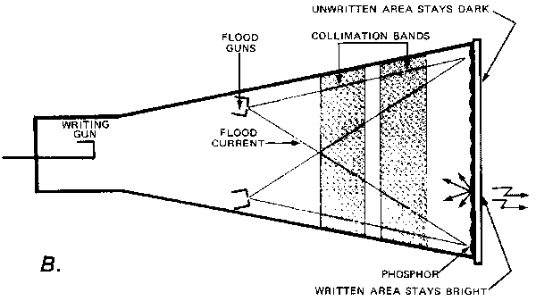
Flood gun electrons hit unwritten areas too slowly to light phosphor and the target charges negative. The positively charged written area attracts electrons at higher speed, keeping the phosphor lit and dislodging enough secondary electrons to hold the area positive.
As the sweep rate of the writing beam increases, a maximum limit is reached where it is difficult to store a display. This limit is specified as stored writing speed. There are two techniques which can increase the stored writing speed limit. For repetitive sweeps, integration can be used. In this technique, the flood guns are momentarily turned off and repetitive sweeps are allowed to build up the charge on the target. If the charge is allowed to build up sufficiently, the written area of the target shifts to the stored state. Then, the flood-gun beam is turned on again to view the display. The second method of increasing the writing speed is called enhancement. This method is intended for use with fast, single-sweep displays only. Again, the writing beam may not shift the target area positive enough to store the trace. To aid in storing the partially written trace, an enhance pulse is applied to the target area during the sweep time. This pulse raises the target positive enough to shift the partially written trace into the stored state. A stored display can be erased by first raising the collector positive so the entire screen is fully written. Then it is dropped negative to about the potential of the flood-gun cathodes and slowly returned positive to the ready-to-write level.
To operate either half of the screen in the conventional (non-store) mode, the collector is dropped to a level close to the flood-gun cathodes. This prevents the target from being held in the stored state by the flood-gun electrons.
PRINCIPLES OF HALFTONE TRANSMISSION STORAGE
(VARIABLE PERSISTENCE)
The halftone transmission storage tube has a basic structure similar to the direct-view bistable tube. Two mesh-type elements are added in this tube near the faceplate to achieve transmission storage. The mesh nearest the electron-gun structure is a fairly coarse mesh which serves as the collector electrode to accelerate electrons toward the storage target and to collect secondary electrons emitted by the storage target. The second mesh is very fine (about 500 lines/inch) and serves as the storage target. A highly insulative dielectric layer is deposited on this mesh using thin-film techniques. It is on this dielectric layer that storage occurs.
In the storage mode, the flood guns cover the entire storage target with a continuous stream of low-velocity electrons. However, these electrons are prevented from reaching the phosphor screen unless a display has been written on the storage target. As the writing beam is scanned across the storage target, it dislodges secondary electrons from the dielectric (see Fig. 2A). These written areas charge positive while the unwritten areas remain negative.
An accelerating potential of approximately 7 kV exists between the storage target and an aluminized layer which is deposited over the phosphor. This potential attracts flood electrons through the written area of the storage target, to the phosphor screen (Fig. 2B). The flood electrons are blocked by the unwritten areas of the storage target so these areas of the phosphor remain dark. The result is a bright, high contrast display of the image originally written on the storage target.
The density of the writing beam striking the storage target determines the amount of positive charge on the dielectric. This positive charge, in turn, determines the amount of flood electrons reaching the phosphor and thereby determines the brightness of the stored trace. It is this ability to store and display changes in intensity that leads to the name halftone transmission storage.
The entire stored image can be erased by applying a positive pulse of about 10 volts to the storage target mesh. Although the dielectric is insulated from the storage target mesh, it goes positive also by capacitive coupling. However, the dielectric immediately begins to discharge back to about zero volts due to the flood gun electrons which are striking it. After about one-half second, the positive erase pulse is removed and the storage target mesh drops back to a quiescent level near zero volts. Again by capacitive action, the dielectric follows negative to about —10 volts. The storage target is now in a ready-to-write state.
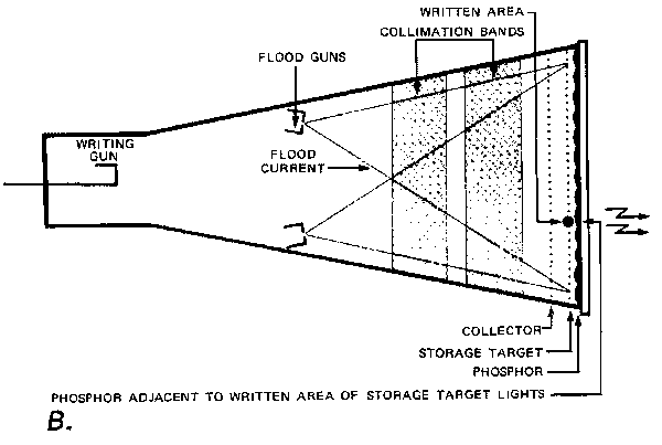
Fig. 2. Halftone transmission storage.

Writing beam dislodges secondary electrons from storage target. The written area charges positive while the surrounding area of storage target remains negative.
Flood gun electrons pan through written area of storage target and strike phosphor. Remainder of storage target blocks flood electrons.
Flood gun electrons pass through area of storage target and strike phosphor. Remainder of storage target blocks flood electrons.
A characteristic of the halftone transmission storage tube is that unwritten areas of the storage target begin to fade positive due to positive ion generation in the flood electron system of the tube. As a result, the entire screen reaches a stored condition after only a few minutes and the desired image is no longer visible. To prevent this from occurring and to provide for optimum viewing of the stored image, the entire screen is slowly erased during operation. This is done by applying variable-width erase pulses to the storage target every 10 ms. Each time a pulse is received, the storage target is partially erased. As the width of these pulses is increased, the display is erased more. Varying the setting of the front-panel PERSISTENCE control changes the width of the erase pulses and, hence, the time that a stored image can be viewed. The few flood electrons collected by the dielectric during each erase pulse cancel the effect of the ions, producing long term stability of the target.
A display can be retained for longer viewing by pressing the SAVE button. This interrupts the variable-persistence pulses and disables the ERASE button. Maximum retention is provided with the SAVE TIME control set to MAX. This removes the display completely from the screen. The display can be viewed by turning the SAVE TIME control clockwise until the trace is displayed at the desired brightness. The display will begin to fade positive after a short time due to positive ions. The viewing time in the SAVE mode is a function of the displayed intensity.
TRANSFER STORAGE
Principles of Transfer Storage
Recent developments in storage at Tektronix, Inc. yield the fastest stored writing speed yet achieved by a storage instrument—a phenomenal 200cm/ps (222 div/la at 0.9 cm/div) with the 7623 Option 12. Based on a transfer storage concept, the 7623 combines many of the advantages of both halftone transmission and bistable storage to produce this ultra-fast storage. Although similar types of storage have been used before to store relatively slow signals, Tektronix, Inc. has refined the techniques to make them applicable to storage of high-speed oscilloscope displays.
The transfer storage tube uses a third mesh in addition to the two used in the halftone transmission tube. The mesh closest to the electron gun serves as a collector. The second mesh is the high-speed target and is similar to the storage target in the halftone tube. The additional mesh is a bistable target which is constructed in a manner similar to the high-speed target but differs in the operating potentials applied.
Storage of a trace on the high-speed target is basically the same as in the halftone transmission tube (see Fig. 3A). This target is very sensitive so that even slight levels of writing beam current affect its charge level.
After the trace is stored on the high-speed target, it is transferred to the bistable mesh (Fig. 3B). If it were not transferred, it could be viewed for only a few seconds before the display would begin to fade positive. To transfer the stored image, a very high-level positive pulse is applied to the bistable target. In a normal bistable tube, this action would completely write the bi-stable target. However, since the high-speed target passes flood electrons only where the trace has been written, this is the only area that stores on the bistable target. The high-level transfer pulse insures that all written areas of the high-speed target, even those with a very slight positive charge, result in a transferred trace on the bistable target.
Fig. 3. Transfer storage.
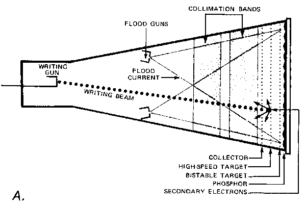
Writing beam dislodges secondary electrons from highspeed target. The written area charges positive while the surrounding area of high-speed target remains negative.

Flood gun electrons pass through written area of highspeed target end strike bistable target dislodging secondary electrons. Remainder of high-speed target blocks flood electrons.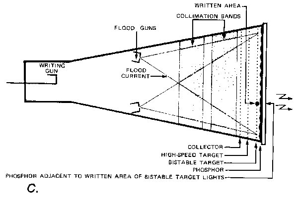
High-speed target Is raised positive to allow all hood electrons to pass. Written areas of bistable target pass more electrons than unwritten areas, producing a trace on the phosphor.
The final step in transfer storage is to lower the potential on the bistable target to a normal viewing level while increasing the potential on the high-speed target. The high-speed target now allows all of the flood electrons to pass. However, the written areas of the bistable target allow snore flood electrons to pass than the unwritten areas, producing a trace on the phosphor (Fig. 3C). Note that bistable storage takes place on a mesh and that a transmission process is used to display the stored trace on the phosphor. Therefore the action taking place is bistable transmission storage.
Since the final image is stored on a bistable storage target, it can be viewed for as long as desired without deterioration in image quality. A 7 kV accelerating potential between the bistable target and the aluminized phosphor results in a bright display.
The intensity of the stored image can be varied with the front panel STORED INTEN control. When the trace is no longer desired, it can be erased. Erase sequence for the high-speed target is essentially the same as for the halftone transmission tube, while the bistable target is erased in a manner similar to the direct-view bistable tube.
Storage Display Modes
The 7623 offen several storage display modes to accommodate a wide range of storage measurements. The fast storage mode always operates in a single sweep manner where a trace is stored on the high-speed target, transferred to the bistable target, and then viewed as long as desired before manual or automatic erase. During view time, the time-base unit is locked out so further traces cannot be stored; it is "armed" so it can produce another trace after the erase cycle is complete.
Normally, pressing the ERASE button erases both the fast and bistable storage targets. Pressing the MULTI FAST button changes the erase cycle so only the high speed target is erased each time the ERASE button is pressed. After a trace is stored on the high-speed target and transfer is complete, further traces can be stored by pressing the ERASE button; the bistable target is not erased. This permits multiple traces to be stored on the bistable target and displayed on the phosphor screen.
Another change in the operating cycle is effected by pressing the INTEGRATE button. This action turns off the flood guns and interrupts the transfer pulse, allowing several traces to build up the charge on the highspeed target before being transferred to the bistable target. Integrate time is limited to only a few seconds in the fast mode.
In addition to the fast storage modes the 7623 provides bistable and halftone storage. In these modes the highspeed storage target is held at about the same potential as the collector and has essentially no effect on operation. The operating potentials on the second storage target determine whether the tube operates in a bistable or halftone storage mode.
SUMMARY
Each type of storage has application areas for which it is best suited. Direct-view bistable storage offers low-cost, long viewing time and split-screen operation.
Halftone storage offers bright, high-contrast displays with variable persistence and the ability to store changes in intensity levels. Transfer storage provides both bistable and halftone storage, plus fast storage to store and display traces as fast as 200cm/as for as long as desired.
With these three types of storage, in six new 7000 Series instruments, Tektronix, Inc. offers you the best in storage, no matter what your application.
ACKNOWLEDGEMENTS
Three concurrent design projects such as the 7313, 7613, and 7623 involve a lot of people. Although we cannot list all of the people involved in these projects, we would like to give credit to the following:
The new CRT for the 7623 was developed by Gary Siewell, Chris Curtin, and Wes Hayward. Wes also contributed much of the technical information for this article. Larry Virgin designed the 7613 CRT. Electrical and mechanical design of the 7623 and 7613 was as follows: Project Engineer was Bill DeVey under the direction of Oliver Dalton. John Durecka did the electrical design. Doug Giesbers, Ed Wolf, and Chuck Davis provided the mechanical design. Aiding the overall design effort were Dave McCullough and Dick Anderson.
John McCormick served as Project Engineer for the 7313. Tim Boege did the electrical design while Cathy Weinstein worked on the mechanical design. Paul Jordan also assisted in this project.
To thank the Author because you find the post helpful or well done.