Trochotron Beam-Switch Counter
Trochotron Beam-Switch Counter

The trochotron is a true miracle of ingenuity, a divide-by-ten high-speed counter in a single vacuum tube, fully exploiting the combined influences of magnetic and electric fields on electrons moving in a complex electrode structure. For some aspects it resembles the multi-cavity magnetron, but here the electron flow is fully controlled and at any time precisely addressed to the selected electrodes, in a fantastic equilibrium play. Nonetheless it never gained popularity, its use being confined to very few niche applications. Soon it disappeared, early victim of the migration to solid state, but many people never heard of it. Today a little more than its fascinating name survives, since even the simple documentation of many types is no longer available.
This overview would be either a synthesis of the few available information on these weird tubes and a possible repository for people who possess further data about.
History and basic structure
Trochotron was the trademark for a little-known hot-cathode counter tube, in which electrons move along trochoid-like trajectories, under combined electric and magnetic fields, in a special electrode structure. Probably it was a by-product of investigations in progress around the late ‘40s on electronic switches, capable of replacing mechanical or capacitive types, as fast multiplexers for analog signals. Ericsson is credited of early investigations on these devices, even if we find remarkable interest by other manufacturers. In Electronics, August 1951 this article describes a very complex electronic 25-line multiplexer, devised by B.R. Shepard at General Electric. Electrons in the beam-switch tube were focused and directed by an external magnetic field, perpendicular to cathode, to flow through one out 25 grid systems, before reaching a common plate. Actually, since the magnetic focusing generated a double ended beam, the number of grid systems was doubled, two opposite grid pairs being driven by each input-channel amplifier.
In 1956, five years later, National Union registered its 25-line data multiplexer, the 6324, very similar to the GE prototype, if not the same.

Fig. 1 – The National Union 6324 intended as 25-line data multiplexer.
As far as we know, none of early Ericsson structures led to commercial productions. ‘Pulse and Digital Circuits’ by Millman and Taub describes a sleeve-anode two-electrode device, similar to the one devised by Backmark at Ericcson. It was a crude structure, yet it was characterized by stable states when used as divide-by-ten counter. Since no grid was available, negative input pulses were applied to the common anode.

Fig. 2 – Left: field distribution in the above two-electrode beam-switch counter. Right: circuit to use the same tube as counter.
The first commercial beam-switch tube, specifically designed for use as counter, was advertised in May 1955 by Haydu Brothers in Electronics magazine. George and Zoltan Haydu in Plainfield, NJ since WWII built special parts for vacuum tube industry: electrodes, spacers, electron guns, up to magnetron anode blocks and to glass-blowing machinery, even contracting small runs of special tubes for large manufacturers. Probably they were involved in prototyping trochotron samples for the Burroughs Research Center. More or less around 1955, when decided to build its own tubes, Burroughs bought the entire Haydu plant, leaving its direction to the same founders for a while: details of the merging are not known. The early trochotron was advertised in May as ‘Beam Switching Tube’, but a couple of months later it was referred to as ‘Magnetron Beam Switching’ or MBS tube. It was claimed to replace 152 components, including 22 vacuum tubes. In December of the same year the MBS appeared in the pages of Electronics with its proprietary code, H-B 101, where the prefix H-B stays for Haydu Brothers, and with its RMA-EIA registration as 6701. In the same page the H-B 101 was associated for the first time with the HB 106 Nixie numerical indicator, the very early nixie later even known as 6844, in a complete ‘Varicount’ counting module. One year later the Haydu brand would definitely disappear, replaced by the corporate Burroughs symbol.
 |
 |
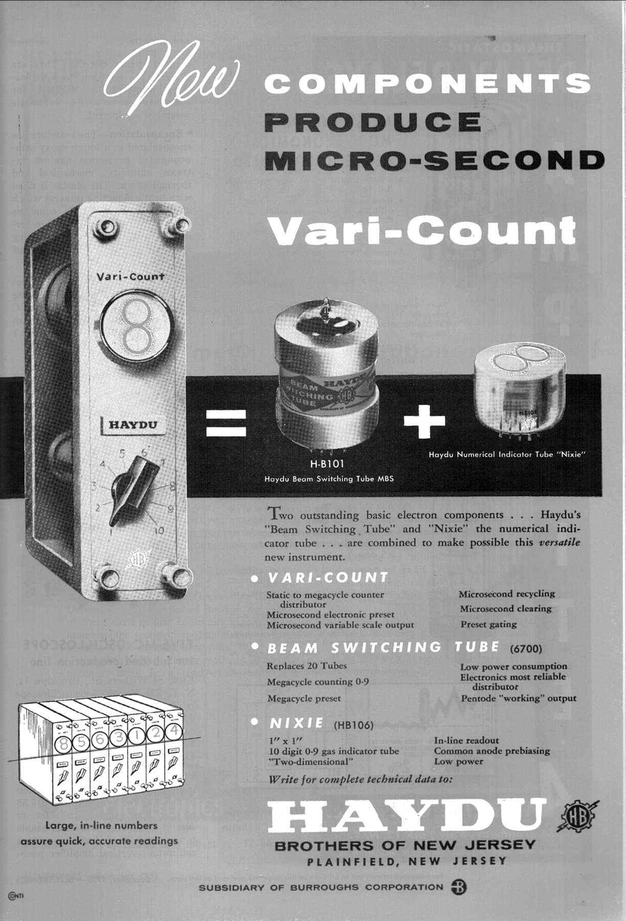 |
Fig 3 – The three Haydu ads in ‘Electronics’ magazine during 1955.
For each count position the 6700 MBS used the three-electrode structure devised by Fan and Kuchinsky at the Research Center of Burroughs in Paoli, PA. To understand its operating principle we refer to the figure below, illustrating the internal structure and the connections of a typical trochotron.

Fig. 4 – Electrodes of a divide-by-ten trochotron, with part of supply buses. The target is ‘L’ shaped, with fin penetrating in the back the spade, to prevent electrons from escaping toward the glass envelope.
An inner ring of ten V-shaped spade electrodes S0 to S9, one for each counting position, surrounds the cathode. Ten electrodes, called targets, are all around, each target partially shadowed by the corresponding spade. A grid rod is between each target and the successive spade. All odd grids are connected together to a base pin and all even grids go to another pin. Typical supply voltage from 26 to some 200 volts is required, depending upon the magnetic field. Targets are fed through load resistors of relatively low value, while the value of load resistors to spades is much higher, typically 100 kohms or more. The glass envelope containing the described electrode structure is immersed into a cylindrical magnet, flux lines being parallel to the cathode itself.
Depending upon operating conditions, this tube has several operating modes, even oscillating ones. Here we try to give an intuitive description of its operation as counter, according to the notes of the same Kuchinsky. At power-on, under the combined influence of the external magnetic field and of the electric field generated by the 10 spades, the tube is in a cut-off state: electrons are forced by the magnetic field to follow quasi-circular equipotential orbits in a dynamic equilibrium, in the region between spades and cathode. Due to their curved trajectories and to the shape of spades, influence from the targets in the background is barely noticeable.
The initial zero condition is set pulsing the S0 spade low for a short while. Electrons spiraling in its vicinity, now feel the influence of the electric field from the target T0 behind, their trajectories being modified due to the target attraction. Subsequently their flow deviate to T0. Due to the curved trajectory, about 15% of total electrons impinge the spade S0, holding its potential low even after the reset pulse. The resulting current distribution to the target T0 and the spade S0 is roughly illustrated by the dashed path starting from the cathode in the figure above. This is a stable state and the current through the selected target is approximately constant, in the order of some milliamperes.
The switching grids are driven by a bi-phase sequencer, which supplies negative pulses alternately to the even and to the odd grid buses. A negative pulse of suitable amplitude applied to the grid close to the holding spade counteracts the attraction of the selected target, releasing the beam from the target itself. Repelled electrons, due to the rotating trajectories imposed by the magnetic field, move then to the leading spade. The current increase through the spade cause a remarkable drop of its potential and the beam is then attracted by the corresponding leading target in the background. A new stable condition is then reached at each counting pulse.
Trochotrons found some niche applications in high speed, top price counting equipment. These devices were bulky and expensive when compared to gas counters, as the dekatron, but were capable of operation at frequencies as high as 10 MHz. A drawback in the use of Trochotrons was the need for a quite expensive Nixie tube when visual indication was required.
Overview of known types
The early trochotron line includes:
- HB-100/MO-10/6700, the basic type capable of operation up to 2MHz.
- HB-101/6701, low-voltage variant operating up to 1MHz at 26 volts.
- 6703/BD-301, similar to 6700 with addition of magnetic shield.
- MO-10R, with built-in spade resistors , capable of operation up to 10MHz.
- BD-309, the shielded variant of the MO-10R.

Fig. 5 - Pictures of 6700, 6701 and 6703
Note the multiple coding for the 6700 and 6701, probably due to the migration from the Haydu proprietary code, to an intermediate Burroughs proprietary, up to the EIA registration.
In order to reduce the size of its counters Burroughs introduced a redesigned family, derived from 6700 and 6703, with scaled down electrode spacing and glass bulb shrunk few millimeters over the base. Known types using the new design are:
BD-203, the unshielded variant of 6700.
BD-316, the shielded version.

Fig. 6 – Picture of a shielded BD-316
In 1960 Burroughs renewed the family adding the compact Beam-X types. Moving the magnet sources into the electrode structure, the diameter of Beam-X trochotrons was scaled down to about the size of a 9-pin miniature tube. Here 10 small magnetic rods were placed behind the 10 spades, even operating as targets. Both unshielded and shielded versions were available. Cross-section of a Beam-X counter is given below.
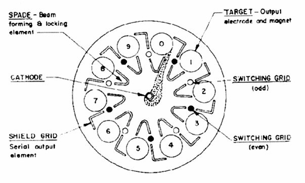
Fig. 7 – Cross-section of a Beam-X counter. Here the required magnetic field is generated by thin magnetic rods, the circles numbered 0 to 9, even used as targets. Ten L-shaped shield grids in the background capture electrons escaped from the electrode interaction space.
Few of the surviving Beam-X types are documented. Their proprietary code starts with the prefix ‘BX’, followed by four digits. Looking at the known types, the first digit should indicate the presence of magnetic shielding and the operating voltage, according to the table below:
BX 1… - Unshielded type, standard voltage
BX 2… - Magnetic shield, standard voltage
BX 3… - Unshielded type, low anode voltage
BX 4… - Shielded type, low anode voltage
Some of the known types are:
BX1000/6710, the basic unshielded type, capable of operation up to some 3MHz.
BX2000, the basic shielded type, same electric specs of BX1000
BX2003, BX2004, BX2005, all not documented.
BX3000, low-voltage, 26 volts, unshielded type

Fig. 8 - Pictures of BX1000 and of some shielded types.
Trochotron tubes were too expensive to be widely diffused. Yet we find productions by European manufacturers. The Mullard/Philips ET51, also approved as CV5277, was equivalent to the 6700. Other equivalents were the Ericsson (ETL) VS10G, its shielded variant VS10G/M, the high-current VS10H and the low-voltage version VS10GK.

Fig. 9 – The Mullard ET51 compared with a Burroughs 6700.
Typical applications
Luckily I recently found a couple of counters, both built around trochotrons. The first one is the FR-114U, part of AN/TSM-16 frequency meter, manufactured around 1960 by Van Norman Industries. It accepts input signals from 20Hz to 1MHz. The set is now fully operating and complete with its technical manual. It was an incomparable help to understand how these tubes were actually used, well beyond the typical applications found in the scarce existing documentation.
 |
 |
 |
Fig. 10 – Pictures of the FR-114U frequency meter.
Count or frequency is displayed by six 6844 Nixie displays, each driven by a counter module based upon a selected 6703 trochotron. Five modules are rated for operation up to 100KHz, while the first one, corresponding to the least significative digit, is rated for 1MHz. Each counter module interfaces through a couple of connectors, the top one to the corresponding display and the bottom one to signal and supply buses.
 |
 |
Fig. 11 – Picture of a 100Kc counting module and diagram of the same.
From the diagram above we can see the interface signals of each module to mainframe and to other modules. Just four signals are required, all through the bottom connector:
- Pin 1: Output signal, from target T(0) to the following stage
- Pin 4: Input signal, from the previous stage
- Pin 6: Clear input pulse
- Pin A: Reset input pulse
Operation is controlled by a sequencer generating timings for reset, count and display states. To initialize trochotrons, before each count, two steps are required: clear and reset. The positive clear pulse, applied to cathode of trochotrons, unlocks electrons from any target previously engaged. Trochotrons return in cut-off state and can now be initialized to their ‘zero’ count. This is accomplished by a negative reset pulse to the ninth spade S(9). The same pulse also sets the input signal flip-flop to its ‘even position’, so that odd grids in the trochotron are negative and even grids are positive. Due to the polarity of grids, the beam skips T(9) and locks to the next target T(0), ready to start a new count. Modules operate with +180 and –120 volts supply voltages. Total voltage, 300VDC, feeds counters through about 36 kohms target loads and 18 kohms cathode resistors. The spade resistors, 150 kohms each, are tied to a voltage divider at about 100V, referred to cathode.

Fig. 12 - Schematic diagram of the reset sequence generator. A single 2D21W thyratron generates both the clear and the delayed reset pulses.
The input signal is fed to the bi-phase counting flip-flop and then, through cathode follower buffers, alternately drives even and odd grids of the associated trochotron. The output signal to the next module is derived directly from the T(0) target.
The second set, using 6700 trochotrons, is a six digit counter/timer shown in the photos below. I hope to light it, even if the job can be difficult, since no documentation can be found and the same power supply connector is missing.
 |
 |
Fig. 13 – Pictures of the unknown 6-digit trochotron counter.
References:
Millman and Taub, Pulse and Digital Circuits
Burroughs datasheets and application notes
TM 11-6625-218-35 Field And Depot Maintenance Frequency Meter AN/TSM-16
To thank the Author because you find the post helpful or well done.