USA 'Project Tinkertoy"
USA 'Project Tinkertoy"

Fellow Radiophiles,
Georg Richter has posted an interesting old article that described the American 'Project Tinkertoy' from 1953 in the German press. I have added a few photos of a module that I own, to his thread.
I read George's article with Google-Translate, as usual, but some words did not translate properly. But the translated content was still worth reading.
Google returned a few interesting hits:
An article from Popular Mechanics published in June of 1954 page 84, and now avaialbe on Google-Books: "Is the Automatic Factory Here?"
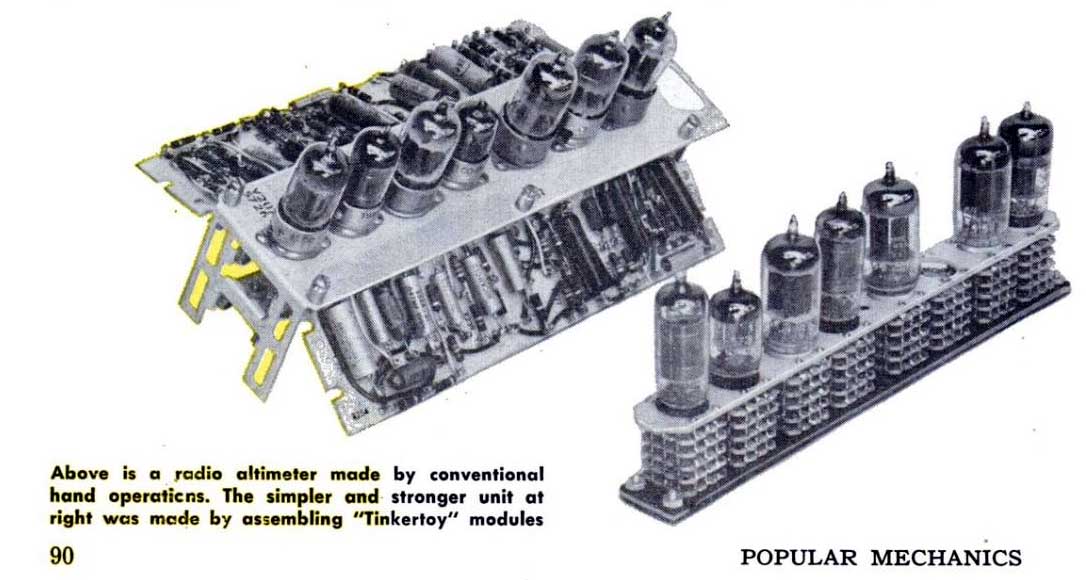
Near the end of this article on page 90, there is a picture of a "radio altimeter" module that looks just like my module, and there is also a picture of the same "radio altimeter" in conventional construction. See George's post for more photos.

Quoting from the 100th anniversary website for NIST "National Institute of Standards and Technology":
"1953
Pioneering Modular Electronics
Tinkertoy meant a lot more than child’s play at NIST in 1953, when a project named after the toy construction sets mechanized the production of modular electronics, a step toward the ubiquitous microelectronics of today.
Project Tinkertoy was intended to help ensure national preparedness in emergencies by drastically reducing production lead time and enabling rapid conversions from civilian to military products. The Navy selected NIST to lead the project because it offered the “most advanced state of processed circuitry.” The Institute already had developed a modular design concept and engaged in pioneering work in printed electronic circuits.
In Tinkertoy, automatic machinery attached basic electronic components to ceramic wafers and stacked the wafers into modules, which then were assembled into complete units. The modules were compact and reliable—so rugged that a demonstration radio could be flung against a wall and still play. NIST performed the basic research and development and designed a pilot plant; various companies designed and built the equipment and ran the production line. The manufacturing cost was estimated to be 44 percent lower than conventional processes.
Dubbed the outstanding development of 1953 by the journal of the Society of Manufacturing Engineers, the Tinkertoy process was used to make sonar buoys for detecting enemy submarines. The project also contributed to the development of the first metal-ceramic vacuum tubes. But the fabrication equipment was complex, and the concept was quickly supplanted by transistors and printed circuit boards, to which some of the individual Tinkertoy components were applied."
Regards,
-Joe
To thank the Author because you find the post helpful or well done.
Tinkertoy outcome

The Project Tinkertoy was commissioned to the National Bureau of Standards (NBS) by the Navy Bureau of Aeronautics with the ambitious targets of automated design and highly automated production plant for electronic gears. The project was financed with some 4,700,000 dollars from 1950 to 1953 and a relevant amount was dedicated to build production equipment. Electronics in its October 1953 issue introduces the involved subcontractors.

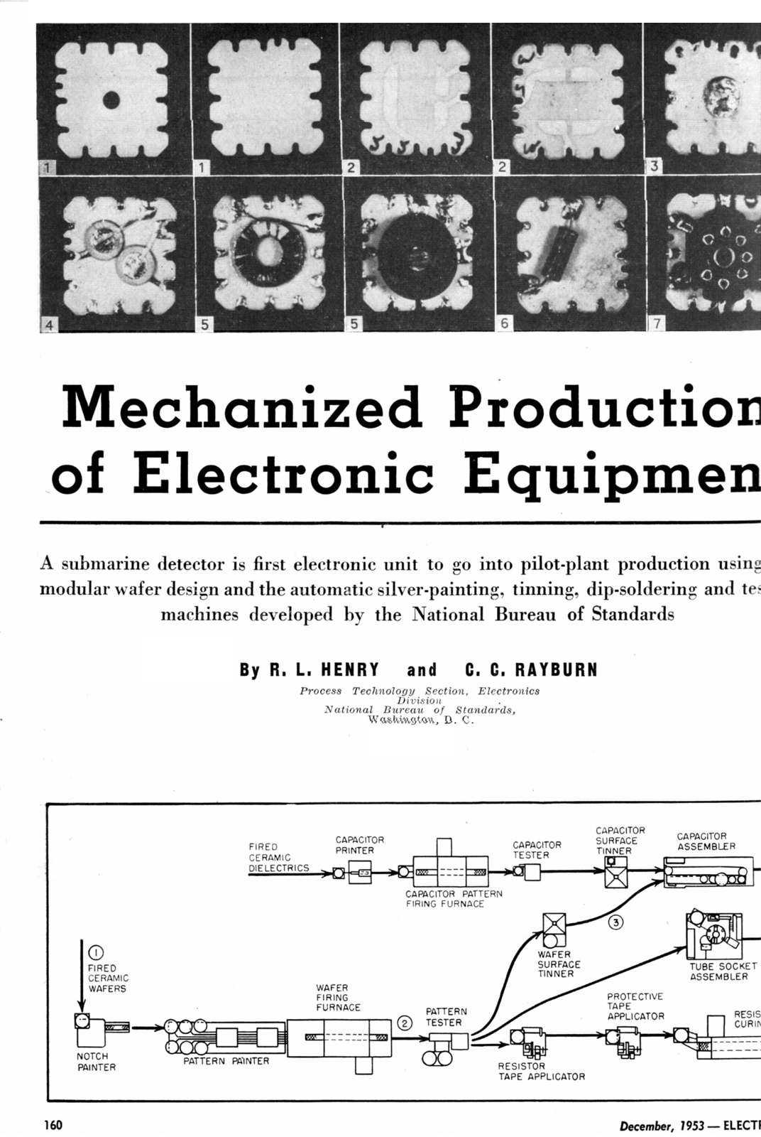
In its December 1953 issue Electronics gives a detailed description of the entire system. The micromodule system was first adopted for the mass production of sonobuoys used by the Navy in large quantities.
Electronics, Dec. 1953, pg. 1 pg. 2 pg. 3 pg. 4 pg. 5 pg. 6
The Tinkertoy Project was intended to standardize the simple electronic circuits of the period. It came too late to compete with new assembly and packaging techniques, made possible by the introduction of printed circuit boards, of thin and thick film hybrid techniques and of semiconductors. Simpler and inexpensive two-dimensional arrays could be easily obtained using different assembly techniques, as small boards plugged on a mother-board. Moreover maintenance was very difficult or impossible for these modules: applications were just confined to high-volume disposable gears. Nevertheless, even if the idea of an automated plant was abandoned, the project left interesting outcomes and the same micromodules were used more or less modified well in the sixties.
Here are some evolutions of the original idea.
a) TIMM or Thermoionic Integrated MicroModule.
In this evolution the same vacuum tubes were integrated in the module. Small heaterless triodes were developed, emission being produced by the heat generated by the circuit itself.
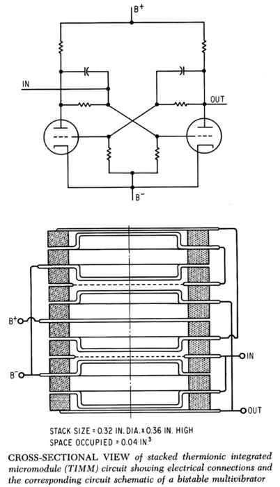
Fig. 1 – TIMM internal section.

Fig. 2 – Picture of a TIMM shift register module.
b) Ceramic tubes.
Navy Bureau of Ships also contracted the development of automated assembly lines for vacuum tubes. Sylvania developed some tubes with ceramic body and stacked electrodes as replacement for traditional glass types. Ceramic spacers and planar electrodes granted excellent performances and ruggedness. The ceramic developmental twin-triode SN-1724D, intended to replace the 6J6, was capable of operating at temperature as high as 175°C and could withstand thermal cycles from the immersion in liquid nitrogen, at -195°C, to boiling water, +100°C, without damages. In August 1954 samples went successfully through a life test at 400°C.

Fig. 3 – SN-1724D ceramic developmental twin-triode.
The above experimental type left two hybrid tubes with stacked electrodes and glass bulbs, the twin triode 7244 and the single triode 7245.
c) Modified Micromodules.
Some of the assembly and packaging solutions of standard micromodules were adapted to more complex circuits and more reliable soldering techniques, as the electron beam welding. Even simple integrated circuits, as flat package DTL ICs, could be mounted on each ceramic wafer. 36 peripheral leads and 20 pin emerging from the base were used in the British variant below.

Fig. 4: A micromodule variant with e-beam welded connections used by Hawker Siddeley Dynamics.
d) Transistorized Micromodules.
Original micromodule packaging system was updated to be used with new transistorized circuits, preserving early wafer dimension. The system was in use until the sixties to build compact and rugged military equipment, including a tactical digital computer.
Here is the RCA specification of the updated micromodule system.
Page 1 Page 2 Page 3 Page 4 Page 5
Here are two pictures of the Micropac digital computer and the diagram of the basic gate (A) assembled in each micromodule.

Fig. 5 – Micropac field digital computer

Fig. 6 – Details of the computer architecture and internal view.

Fig. 7 – Schematic diagram of the basic gate micromodule and of a complete flip/flop.
To thank the Author because you find the post helpful or well done.
Tinkertoy in Motorola portables
Fellow radiophiles,
MAARC (Mid Atlantic Antique Radio Club) newsletter editor, Ed Lyon, has just come across this thread and he sent me an email mentioning his involvement in the modular Tinkertoy development and the existence of single stack modules in late 50's Motorola portables.
I quote here his email sent to me July 19th 2010:
Joe:
I just noticed your entry on the Radiomuseum forum on Project Tinkertoy. I worked at ACF Industries (they had bought our company in 1955) and was an advisor to Bob Henry, who was the NIST (then called National Bureau of Standards) Tinkertoy program founder. He moved from NIST to ACF when the project was assigned there, where his group designed all the Tinkertoy modules, and I have a radio (with a neat plexiglas case) that was made up of these modules. We also had a prototype TV set, made up entirely of these modules, too. There are some Motorola radios that use a module in their circuitry. These radios have the ferrite loopstick antenna built into a rotatable carrying handle on top, and are in the 5P22 to 5P33 series of model numbers. I the website Radio Attic, in the Motorola section, you can click on Model 5P22-1 and there is a picture of the radio, opened up. The Tinkertoy module can be seen in the center, with a tube plugged into it.
I did some articles for Radio Age on Tinkertoy some time ago, and I think Alan Douglas contributed one on that project, as well (Nov. 1993, March 1994, May 2002)
You might want to check out the stuff on Ben Tongue, too. (April 2002, for one such article)
Ed
I did some looking around through our database in the 5P22 to 5P33 model range specified by Ed, and found several late 50's Motorola chassis types with the Tinkertoy single stack modules: HS633, HS647, HS559, HS561.
One of the photos at the model page for 5P31A - HS559 shows one version of the Tinkertoy stack with a tube socket at the top holding the 1DN5 detector/audio-preamp tube.
The schematic page with the top view of the parts layout for model 5P21B - HS633 shows a different Tinkertoy single stack module without a tube socket.
An inspection of the schematics for these two Tinkertoy module types reveals that nearly all low power resistors and non-electrolytic capacitors are grouped in these modules. These R's and C's are all involved in bias, AGC, or audio functions. The 100k grid leak resistor at the front end converter was necessary left out to avoid parasitic capacitance and coupling troubles.
The virtual absence of discrete resistors in the radio reminds me of 1920's battery radio designs, where, often, the only discrete resistor was the grid leak.
This grouping of R's and C's serves to illustrate the impact that the introduction of the Carbon Composition resistor around 1930. The carbon composition resistor became the versatile component that set all bias levels, AGC, and audio filtering and coupling.
Two key characteristics of carbon composition resistors were it's availability in values from 10Ω to tens of MΩ, and the absence of capacitive and inductive parasitics. Much lower cost than precise, but parasitic ridden, wire-wound types, was also essential.
The introduction of the Carbon Composition resistor was explored earlier.
Regards,
-Joe
To thank the Author because you find the post helpful or well done.
More Tinkertoy modules found
Fellow Radiophiles,
Ed Lyon has sent me another interesting email that I quote here with his permission:
Joe, I found a page of those tinkertoy modules, marketed by
Aerovox (but probably built by ACF Industries), on Page 110 of the Radio Shack 1958 Catalog. They listed 8 different modules (two linear amplifiers, one phase inverter/driver amplifier, one flip-flop, one dual high-level cathode follower, one +150-volt regulator, one monostable multivibrator, and one phantastron).
Interestingly, EECo also listed similar circuits in the late 1950s and 1960s, but all mounted in aluminum fixtures with octal (and nonal and decal) bases.
In February 1958 I had to take an unfinished radar to Johnston
Island in the Pacific. I knew I still had to design and build the synchronization circuits, the pulse modulation circuits, and the range gating and range marker circuits before we could try the radar, but time had run out, and we had to take the system to Johnston Is. I packed a big box of assorted EECo modules,
and a big chassis, prepunched with 20 octal socket holes with sockets, and an integral power supply. Once at Johnston, my co-workers began assembling the antenna and feedline system, and I began designing the radar “digital” circuits, and then built them, using all EECo modules. It worked well, and I sent the schematic and photos back to the factory, where they duplicated the chassis for another radar our company had to install in Maryland. Today a simple FPGA would do all those functions, and be software controlled.
Ed
Some of my response to Ed:
Ed, your email is of interest to the RadioMuseum.org and to the Philbrick Archive. The latter is because I have come to collect a big pile of EEco and Walkirt modules. See the end of Philbrick Archive.
One set of my Walkirts came assembled in a 4 bit counter that I fired up and got running. An idea just came to me for a use of this counter, and that is to use it as a soldering iron timer. The purpose of the timer is to extend tip life, not safety. I will, of course, have to add some suitably showy neon bulbs to indicate count state.
The Tinkertoy module descriptions that Ed mentioned at the top of page 110 of the 1958 Radio Shack catalog can be seen at Michael D'Alessio's very fine archive of Radio Shack Catalogs.
Regards,
-Joe
To thank the Author because you find the post helpful or well done.
Tinkertoy Radio

In my collection, I have a Tinkertoy radio, one of apparently three, made by the government to demonstrate the application of the technology to commercial producers. I know Motorola made some portable models using the technology. I also ran across what is apparently a servo conrtoller, using the technology, which comes from the estate of an engineer who was involved in the development of remote steering for missiles in the early 1950's. I include pictures of the radio and the servo controller. I have also included pictures of the Motorola 66L2, which includes the technology.
Attachments:- back of radio (142 KB)
- servo front (170 KB)
- side of servo (236 KB)
- Front of Tinkertoy radio (262 KB)
- Front of Motorola 66L2 (201 KB)
- Chassis of Motorola 66L2 (228 KB)
To thank the Author because you find the post helpful or well done.
Autre famille de micromodules

Dans les années 60 et 70, la société française Precilec a construit des modules du même genre sous le nom de NORMOD. Elle travaillait sous licence de la société américaine NORDEN, située à Norwalk, Connecticut, membre du groupe United Technologies.
C'était le même genre d'empilage de plaquettes en céramique pour réaliser des fonctions élémentaires telles que basculeurs, portes, amplis-op, etc, mais il s'agissait de semi-conducteurs et non de tubes. Si je me souviens bien, la logique était en DTL.
C'était destiné au marché militaire, avec des conditions d'environnement particulières : température, chocs, vibrations.
Quelqu'un en a t-il déja entendu parler et pourrait donner des détails ?
To thank the Author because you find the post helpful or well done.
Aerovox TinkerToy at Radio Shack in 1958
Our RM founder, Ernst Erb, has told me via email that the 1958 Radio Schack sold a range of Tinkertoy modules, that were made by Aerovox. Note that these modules were mostly for audio and industrial applications. However, Motorola model 66L2 also had a local oscillator module with integral LO coil.
It is remarkable that all 5 tube functions, including the power rectifier, were fitted with a TinkerToy module as shown by Gerhard in the attachments of post#5.
See Page 110 of 1958 Radio Shack catalog hosted by Mike D'Alessio at RadioShackCatalogs, and reproduced here with permission. (click to enlarge)

Regards,
-Joe
Attachments:To thank the Author because you find the post helpful or well done.