Invention of Resistor
? Invention of Resistor

Dear Radiophiles,
When were carbon composition resistors invented?
They were one of the key technologies that separate 1920's radios from all later designs.
The carbon film resistors used in 1920's grid-leak detectors were a specialized item that only came with less than a decade of range in high values, from 100's of kOhms to a few MegOhms.
Were the Resistors in the 3NF integrated tripple triode amplifier, the first mass produced carbon composition resistors?
Carbon composition is a semiconductor. This explains the ease of coverage of many decades of values, as opposed to metal wire wound resistors which were suited only for a couple of decades from a few Ohms to a few hundred Ohms. Higher valued wire wound resistors were too expenisive for radio work, and had very poor AC performance.
Carbon resistors had stelar HF performance compared to wire-wound types, and opened up a revolution in Audio design, power supply design and bias supply design. It also afforded unprecedented freedom in parametric control of all tube stages.
This question has bearing on the thread discussing untuned RF amplifers.
Regards,
-Joe
To thank the Author because you find the post helpful or well done.
Silicon Carbide Rod resistors

The first high-ohmic resistances known to me are rods of compressed powderized silicon carbide, what in German is called a "Silit-Stab". The material is well known as a semiconductor, and these resistors were known for giving different resistances at different applied voltages. They were used as grid leaks, and as plate resistors in R-C-coupled tube amplifiers. The are in fact similar to modern VDRs.
I believe I have seen them in schematics as early as the 1910´s to bleed off static charges from antenna circuits.
The resistive properties of arc-light carbon rods were well known by the end of the 19th century. In the form of the carbon microphone carbon resistance materials were also well introduced into telecommunications.
I just wonder who made the step from massive rods with metal caps on their ends to carbon film resistors with a ceramic body covered with a thin layer of carbon, eventually with a spiral groove for trimming.
Yours,
Nikolaus Loewe
To thank the Author because you find the post helpful or well done.
BradleyOhm & BradleyStat
Thanks for the added info about the silicon carbide resistors. This helps widen the context of the development of the Carbon Composition resistor.
Wikipedia (english) says that thick film resistors came into use in the 1970's. The carbon film on n leaded cylindrical carbon film resistors is a thick film that is applied in liquid or paste form, and later cured. This is the most common film used in inexpensive modern SMT resistors.
Carbon film when compared to Carbon composition, seems an improved method, sharing many of the same characteristics. The leap from metal resistors to semiconductor carbon composition resistors was a great leap.
I remembered that I own a few BradleyOhm and BradleyStat two-terminal variable resistors from the 1920's. I came across the first of this type in a Browning-Drake Neutrodyne-Regenerative set owned by my friend Ron Roscoe. I restored the BradleyOhm resistor by disassembling and cleaning the contacts to the two piles of carbon disks that form the resistor. I replaced the rivets I drilled out with screws. The value of resistance is changed by variation of preasure applied by an external screw to a pressure bar that straddles the two disk piles. The terminals are taken at the bottom of the two piles. This Bradley-Ohm variable resistor was in series with the regenerative detector plate, and ranged in value from a few K to almost 100k.
At the time of the restoration, I took pictures of the disks, but seem to have lost these photos. Perhaps Ron will send me back some copies of the photos for posting here.
Since then I bought a few examples of these pots in three different value decades. The value version was marketed as a BradleyStat because it was in the low resistance range of rheostats, despite the fact that it was made with carbon disks.
Only two terminnals with multi-turn knobs to thighten the compression screw.
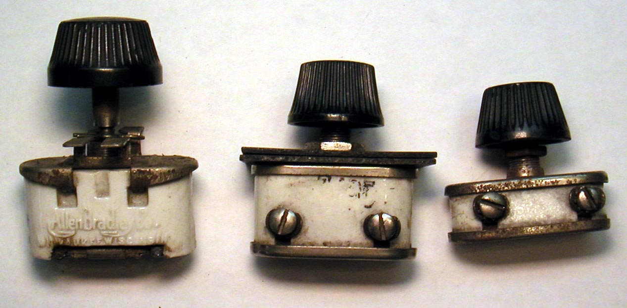
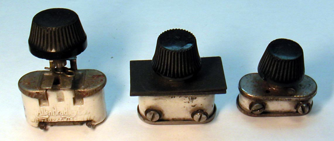
The two resistors on the left include mounting hardware.
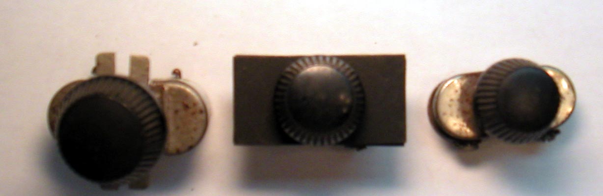

Grid leak resistor with capacitor, BradleyOhm resistor, BradleyStat.
Also note the A-B Allen-Bradley logo.

Left: 100k-10Meg Center: 3.5k-100k Right 7.5_Ohm-120_Ohm
These values were measured. There was no indication of value, otherwise.
The two piles of Carbon disks sit on the ends of the porcelain mold. The compression screw occupies the center space and works against the bottom plate. If the screw is unscrewed too far with the knob, the resistor will become open.
The left most of these pots with a 100k-10Meg range was designed for Grid-leak applications and included an integral capacitor, of a few hundred pF, mounted on it''s bottom plate.
One key step toward the manufacture of Carbon comp resistors is already realized in these pots, and that is the ability to change the bulk resistivity of the disks. A precision of 50% in the bulk resistivity would have been adequate, given the wide adjustability, over one decade. A precision of at least 20% was needed for Carbon-Comp resistors.
Regards,
-Joe
To thank the Author because you find the post helpful or well done.
Variable Grid leaks

Just to mention that "The Radio Trade Directory" lists 35 U.S.manufacturers of variable grid leaks.
I think that there was no other way but the compression method (Variable contact on carbon surface) to achieve such a feature.
In Popular Wireless issues from 1923 ads are found where Lissen offers a Variable Grid Leak (0.5 to 6 MegOhms) and a Variable Anode Resistance (20 to 250 kOhms).
"The interposition of the elastically deformable metal discs - there lies the secret of that perfectly free movement of the whole resistor column...".
Another model is the WatMel variable grid leak.
To thank the Author because you find the post helpful or well done.
? Origin of Carbon resistors
The use of the carbon resistor dates from the 1800s where it was used as a control element in motors and generators. We also have the carbon filament lamp which was also used as a resistance element.
The composition of the carbon elements to vary the resistivity was developed at this time and would have been taken into the later fixed resistance manufacture.
The carbon piles were controlled both manually and also by servo as in the Brush dynamo scheme. They were also used for low-power theatre lighting dimmers.
The need for fixed resistors only became necessary as the thermionic tube circuits progressed from transformer coupled to resistance-capacitance coupled.
###details to follow
To thank the Author because you find the post helpful or well done.
Gridleaks, Transformer coupling and wire-wound
Thank you Konrad and Roy for your contributions.
Now it is clear that when the first fixed carbon composition resistors were developed, there was already a significant production of variable carbon composition resistors with compressible disks.
Roy's comment about the "need for fixed resistors" brings to mind that transformers were still preferable to resistors in 1920's radios for at least two reasons:
The tube gain was low, and the transformer provided "free" gain simply by impedance transformation. Audio voltage gain for a coupling audio transformer was usually between 2 and 4.
Another reason for superiority of transformer coupling in battery sets was that much wasted power would be dissipated on the load resistors. Higher voltages would have to be provided to the audio stages to maintain the plate voltage at the ideal operating point.
It was simply more efficient to have batteries with multiple taps than a network of power supply resistors.
The advent of AC power and higher gain tubes, in the form of higher mu triodes and the pentode, made resistive loading cost effective, and dimished the need for transformers.
Interesting to note that the 1950's and 1960's saw a resurgence of transformer use in low level audio stages with germanium transistors in the low power audio amplifiers of portable radios. Power efficiency was one of the reasons for the resurgence. Resistors, however reigned supreme as the method for individual stage bias.
In my initial post I aluded to the "high cost" of wire wound resistors. While this is true when we think of bias and load resistor use in post 1930's designs, the wire wound resistor carved out a long lasting place in 220VAC/110VAC radios, as the main input series voltage dropping resistor. These resistors had a single layer of NiCr wire over a ceramic tube or slab, with metalic ring taps. Often, there was no protective finish over the delicate NiCr wire.
These power supply tap wire wound resistors even saw use in 1950's and 1960's high precision +/-300V power supplies for analog comptuters. Such is the case of the R-100 and related supplies from Philbrick Researches. Full data on these supplies is availabe at www.PhilbrickArchive.org. These resistors were always finished with a protective layer.
The wire wound resistor always had supperior power dissipation capability, as compared to the carbon composition resistor, and remains in use today in power applications. It can also operate at higher temperatures reliably.
One particular failing of the carbon compostion resistor is a signficant voltage coefficient for voltages in excess of 100V. The resistance may vary up to a few % at 300V. I made some measurements and posted them on my web page www.PhilbrickArchive.org.
Another well known limitation is excess noise that is not predicted by thermal agitation. Effects similar to those that govern the operaition of the Coherer detector may be at work here.
Regards,
-Joe
To thank the Author because you find the post helpful or well done.
BradleyOhm inside
Hello Radiophiles,
The following photos show the interior construction of a BradleyOhm. This particular unit ranged in resistance from a few kOhm to over 100kOHm, for service as a variable plate load resistor.
.JPG) After removing 4 long rivets that hold the top and bottom metal plates together, the two carbon piles are located under the insulating disks.
After removing 4 long rivets that hold the top and bottom metal plates together, the two carbon piles are located under the insulating disks.
The carbon piles are connected by the shorting strap under the insulating disks.
The insulating disks isolates the carbon piles from the pressure strap under the top plate and pressure screw.
The terminal screw heads are just visible and make connection to the bottom of each carbonpile.
This is a two terminal variable resistor; not a three terminal pot.
 Rivet wells make room for the four rivets that must widstand the high forces of the presure screw. Over time the Aluminum rivets have a tendency to loosen, and on some BradleyOhms only 2 rivets were used, leaving two wells empty.
Low values of resistance are obtained at the higher presures.
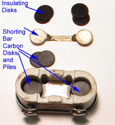 The bulk resistance carbon composition material is in the form of disks arranged in two piles.
Varying the preassure over the carbon disks varies the connection area of the rough surface of the disks, and changes the overall resistance of each carbon pile.
The terminals connect to the bottom of the pile, and the shorting bar connects the two carbon disk piles.
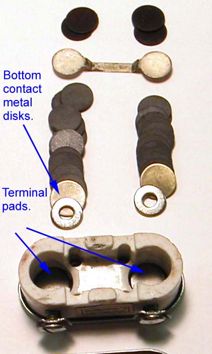 I added two washers to increase pressure in the pile, which had gotten somewhat loosened over time.
It would stand to reason to leave your BradleyOhms under low pressure over long storage periods.
The terminal pads are part of the screw terminal.
The operation of the knob is multi-turn.

Regards,
-Joe
To thank the Author because you find the post helpful or well done.
Resistor history
Jumping in late:
> When were carbon composition resistors invented?
I bet they just evolved. Carbon was WIDELY used for many things. In electricity, for carbon-arc electrodes ("rods"), for motor brushes, and as the "carbon pile" resistor still occasionally seen for testing car batteries (12V 50A-200A 0.24-0.06 ohms 2400 Watts), like your variable grid-leak only bigger. Edison was making money with carbon filaments. Lampblack was a common ingredient in paints, tires, and high-temperature gaskets.
> Carbon composition is a semiconductor. ... the ease of coverage of many decades of values,
No and yes.
Carbon composition isn't an atomic (intrinsic or extrinsic) semiconductor such as we use for transistors, photo-resistors, etc.
Yes, carbon-comp has some of the non-linearity found in semiconductors. But that's an acceptable flaw, not a virtue.
Carbon Comp is a composite of coal-dust and clay. Like making concrete or plastic cups, in addition to basic form-factor (long-thin versus short-fat), you can adjust the ratio of stone/sand/cement or styrene/gas to vary the strength and density. A low-ohm carbon-comp may have a shorter fatter internal rod than a Meg resistor, but you can only take this so far. Adjusting the coal to clay ratio gives another parameter. The low-ohm will be mostly carbon, the Meg will be mostly clay.
> The carbon film resistors used in 1920's grid-leak detectors
I suspect several things have been called "carbon film".
There are thick films applied as a binder or ceramic slurry and fired. Mixing lampblack (carbon dust) with a binder is very old. The problem with high-ohms is that if carbon content is too low, the dust grains may not touch. You can't make high-ohm resistors this way.
With carbon-comp you adjust carbon grain size against clay grain size and then press firmly. The clay flows until carbon-tips touch. With practice you can make very low-carbon mixtures give higher ohms reliably.
1950s or so found a need for resistors of odd shapes and very low parasitics for microwave work. Carbon film was a high price handmade resistor.
> thick film resistors ...1970's. ...a thick film that is applied in liquid or paste form, and later cured. This is the most common film used in inexpensive modern...
I do not think that is correct.
Cheap carbon film resistors: put ceramic bodies on racks in a pot, evacuate the air, bleed in a little propane or other carbon-rich gas, raise the temperature, and then spin the racks. The gas breaks down to atomic carbon which is deposited on the rotating bodies. Simple gas metering systems can repeatably produce a range of carbon thickness and resistances.
> The wire wound ... supperior power dissipation capability, as compared to the carbon composition resistor
I suspect a carbon-comp could be made to any power level. They do not take heat well, so would be bigger than wire-on-ceramic.
Carbon is very brittle, or slightly brittle and very costly. Carbon is not a very poor conductor. For resistances above a few ohms we need a long thin shape. But that's bad in brittle material.
NiChrome is a better conductor but not brittle. It can be drawn into very long thin yet strong wire. Usually too long to be practical, and the thin wire gives little heat dissipation. However it can be wound or bonded to strong ceramic which gives support and shape and heat dissipation area. The wire's elasticity means different thermal expansion of wire and ceramic is not a big problem at quite high temperatures. It may be problematic at very high temperature, but so is the thermal coefficient of resistance (metal resistance rises with temperature), and that's more often the limit in basic iron and NiChrome resistances. (There are low tempco alloys but they are very expensive.) If getting rid of heat is your big problem, NiChrome on ceramic is affordable proven technology.
(At very very high density, for electric furnace heating, you use solid strips of cast iron on refractory insulators. You have to start on reduced voltage because the cold resistance is much less than operating resistance. It's more metal than you need for electrical flow, sized for surface temperature. Even in a non-oxidizing atmosphere the iron rots fast. But cast iron used to be very cheap and readily available, so this was the best BIG HOT resistor.)
No, I think the killer advantage of carbon-comp is that they can be MASS produced at nearly zero raw cost. Coal and clay, even good stuff, is not expensive at this scale. There's an investment in molding machines, but some of these existed from pottery and button production.
Also I believe carbon-comp is "self terminating". If you stick leads in the composition before pressing and firing, you get a good-enough connection with no further work. Compare to welding NiChrome to terminals, a fussy operation; or the assortments of stampings and screws in your variable resistors (not even counting the variable part). Even wrapping leads on radial resistors is an extra step, avoided with carbon-comp.
A "fault" of primitive carbon-comp production is large variability. If all your buyers need 1K +/-5%, your yield is poor. However tube-biasing often allows wide variation from "ideal" value: 500K or 2Meg will hold a grid bias. And the wide variety of new or changed designs meant that nearly any value could find a buyer: Smith Radio used 70K where Jones used 20K with different coil-taps. So you mix a vat of "medium-K" stuff, then sort to 2K, 3K, 5K, 7K bins. (Later this became the 20% no-stripe series and then the 10% on 2K2 2K7 3K3... nominal centers.) Batch control did not have to be very good, because if they were cheap enough you could sell most of whatever came out of the batch.
Yup, when tubes and batteries were costly, resistors were wasteful. In RF, a coil was the same price and worked better. In audio, a transformer worked well and was cheaper than the tube that drove it. With wall-power it became cheaper to resistor-bias than to many-tap the transformer and rectifier. Wall-power brought increased tube production and lower tube prices, when tubes became cheaper than coupling transformers we needed plate and grid resistors and coupling capacitors. Tubes could have used more resistors sooner, but why? Resistors could have been a penny each, but why? It was the late 1920s before it all came together and large numbers of low-price resistors were made.
To thank the Author because you find the post helpful or well done.
Tobe Deutschmann / Loewe resistors

To address the original question, the resistors in the Loewe 3NF look like glass rods with wires embedded in the ends, with a very thin, almost transparent coating , which I assume is carbon.
Loewe manufactured separate resistors in the late 1920s, some of which were imported by Tobe Deutschmann to the USA. These appear to be made in the same way, except that the carbon coating is much heavier. The coated rods are sealed in glass enclosures under vacuum. Their resistances have remained remarkably stable for the dozen or so samples that I own. Two 50k resistors measure 47.5k for instance. 0.25 and 0.5 Megohm are about the same amount low, while two 10 Meg resistors have dropped somewhat more and aren't stable.
A few adjustable grid leaks from the early 1920s used metal wipers against paper coated with India ink. But they didn't work very well or for very long.
By the late 1920s many different methods of making radio resistors were in use. There were thin glass rods coated with carbon, carbon deposited on the inside of glass tubing, carbon rods, and the old standby of paper strips soaked in India ink and held in metal clamps. None of them were very reliable.
To thank the Author because you find the post helpful or well done.
AquaDAG
Then there is AquaDAG, a colloidial suspension of graphite in water (or alcohol or oil). This name is a product of Acheson Industries. I can't trace the origin; I think it goes back to the 1920s. It boomed after 1950 for TV CRT coatings, which moved overseas and then faded, and Acheson has been absorbed into a large company with too many products.
Making low-value resistors is easy with AquaDAG. (This may even be an option for repairing cracked original resistors.)
Small bottle $15
Tech data for PELCO® Conductive Graphite
1:1 dilution, brushed, air-dried, 1 mil film thickness, gives roughly 300 ohms per square. "Square" means you make a flat square sample, contact two opposite edges: resistance is the same for a square 1mm or 100Km on a side. A cylinder 1cm long and 0.318cm diameter has a square surface. A ceramic rod brushed with AquaDAG and end-contacts will be about 300 ohms. Dipping and cooking will give closer to 30 ohms.
You could get lower resistances with thicker coatings. You can get higher resistance with thinner coatings, but uniformity and contact becomes a problem. You can try other shapes but too-tricky gets too-costly. The 1cm*0.3cm rod with a 10-turn helix would give about 30,000 ohms.
The particles are weakly bonded. The coating is fragile. The resistance will change with abuse, mechanical or electrical.
I don't know, but suspect, that some older "carbon film" resistors were AquaDAG or similar. It was available, inexpensive, and obvious.
> paper strips soaked in India ink and held in metal clamps
HUH! Never saw that. But into the 1950s, "resistance paper" was a standard item in EE labs. You could plot 2-D problems in electrostatics with contacts and battery, move a voltmeter probe around and trace the lines of potential.
To thank the Author because you find the post helpful or well done.
Grid Leaks
That would be Teledeltos paper, which I remember as being shiny gray.
DAG is short for Deflocculated Acheson Graphite. From a quick Google search on "deflocculated graphite" I see that the term DAG goes back to 1906.
Here are some representative grid leaks: two with impregnated paper elements, one internally coated and one with a coated glass rod.

To thank the Author because you find the post helpful or well done.
Loewe Resistors

I can confirm the production method of Loewe resistors. From an interview of deceased Bruno Wieneke, a contemporary witness and glasblower at Loewe in the 1920ies I have a descripion of the production process.
In fact they took a glass rod and sprayed china ink (a colloidal dispersion of cabon black) on it. The rods were contacted by a lead cap and moulded into a glass tube and evacuated. Afterwards the resistors were measured and selected, assorted and labeled. It is also possible that they used aquadag later.
The advantage of these resistors was their stability, independed value from applied voltage and they produce less noise than the at that time in Germany used "Silit" resitors. So it is not astonishing that Alan still meassures the labeled values.
Later they used these resistors in the famous Loewe triple valve due to their stability in the valve production process. End of the 1920ies they improved their know how and Loewe multiple valves of that time contain resistors without an extra glass bulb.
The Loewe resistors were a big business sucess. They also produced capacitors in evacuated glas tubes. Several versions are known. With wires, caps and screws.
Rüdiger Walz
To thank the Author because you find the post helpful or well done.
string soaked in ink
> A few adjustable grid leaks from the early 1920s used metal wipers against paper coated with India ink. But they didn't work very well or for very long.
Here is string soaked in ink:

- Variable gridleak (46 KB)
To thank the Author because you find the post helpful or well done.