Vintage Indicators, except mechanical types
Vintage Indicators, except mechanical types
Overview of Technologies for Vintage Electronic Indicators
I studied the subject of Vintage Indicators generally (not just for Tuning Indicators) recently and have this classification:
- Gas Filled, usually Neon
- Vacuum, usually triode type with a glowing target or screen
- Incandescent
- Electroluminescent
1. Gas Filled, Neon, Argon (Article)
Static indicator, on/off only
Tuneon type bar
Russian Bargraph (IN-9, IN-13)
Counting type indicator (Dekatron)
Formed characters (US Nixie 1955 and Russian copies)
Segment Numeric or Alphanumeric (seven Segment, Starburst, Planoplex)
Dot matirx (Plasma Monitors and small indicators like ITM2M as well as single characters)
2. Vacuum, usually triode type with a glowing target or screen
Static indicator (DM160, IV-15), on/off only
Magic Eyes
VFD generally (based on DM160 idea but with segments, since 1960s) Still current.
CRT based dedicated characters (CRT predates Triode!)
CRT
3. Incandescent
Bulbs
Shadowgraphs
Seven Segment
4. Electroluminescent
These are rarely used as actual Indicators but as backlights for mechanical scales (or LCD later) since late 1960s. They have only really changed in reliability and still made today for backlights and large annunciators, even archhitecturally for stair step illumination.
Current: LCD, VFD, LED, OLED
The oldest LCD panels and LED calculator displays are really vintage now. LCD is of course still current technology. OLED has more in common with Organic Electroluminescent displays than with "traditional" LED chips. They just happen to be like diodes and emit light.
Modern VFD are really multiplexed Triodes. Cathodes are fine heater wires
"grids" are 0V or +22V to select "Digit/area"
Anodes are paralled segments in different areas.

Modern VFD and the maybe the first
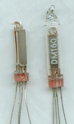
DM160 (28mm tall) 1959
More like a light bulb or Neon Indicator in use the DM160 was just brightness control via grid, no change of pattern or size like the earlier Magic Eye tubes and Tuneon.
Even the later bargraph VFDs after the first 1960s Seven Segment Numeric successors to DM160 on/off indicator are all only on/off segments or vary brightness of entire display. Bargraphs or Meters are created by multiple segment identical style of layout to LCD. By 21st Century the Bargraph is mostly just used for Audio level.
Tuning Indicators
After the era of Magic Eyes "tuning" indicators are mostly just a cheap mechanical meter or omitted entirely. On some radio LED, LCD or VFD bargraph are used. See the main article on History of Tuning Indicators.
Many of the other "vintage indicators" are used only in test gear, calculators, specialist equipment and not as tuning indicators. Probably further writing on the separate types will be in other threads.
In my study of Vintage Indicators (generally, not just tuning) I ignored mechanical meters. Meters have changed mostly just in cost and appearance. I read that the main reason for Tuneons and Magic Eyes was simply that a Meter was more expensive to make than a tube. In the 1970s any tape recorder or Radio with a level indicator or Tuning Indicator appears to have switched to the cheap plastic cased Japanese meters with typically 250uA movements, though they vary from 50uA to 1000uA.


Typical cheap 1mA and 200uA meters.
Scales are also available for Tuning, SWR and VU level.
Historic overview & Timeline

- The top section are the time lines of various indicating and display technologies
- The middle section is the time line of Tuning Indicators for Domestic radio
- The bottom section are times of important related developments.
The times are exact on some things (we know exactly when 405 TV started or Magic Eye Tubes were used). But other things are less exact. Do we mean a discovery by anyone, a demonstration or a product in the shops? Which shops, just in Japan or everywhere?
Also although LED calculators and frequency display on Radio sets largely predate LCD versions by a couple of years there were LCD panels (in a Watch) when LEDs were only individual indicators.
Though the theory of Transistor was maybe in 1930s and demonstrations in 1948, the early transistors could only manage 100kHz. So Pye's PAM710 in 1956 had only 315kHz IF instead of the usual 450kHz to 470KHz. It was not till about 1965 that the valve (tube) finally gave way to the transistor.
Minitron Incandescent filament display early 1970s and earlier Numitron
The RCA Numitron seven segment Filament display was in the very late 1960s (Tube like envelope)
Patents can be good or bad. Perhaps they should not awarded too broadly. Many different shaped neon indicators had been made, yet Burroughs  had control of Nixe tubes and the cost was too high for Japanese calculator makers. The early Nixie displays were made by a small vacuum tube manufacturer called Haydu Brothers Laboratories, and introduced in 1955 by Burroughs Corporation, who purchased Haydu and owned the name Nixie as a trademark. Nixie tubes used an entire shaped character for each digit or letter to be displayed. So everyone else needed an alternative.
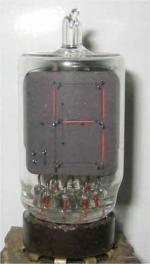
Certainly by 1963 the Japanese had developed the 1959 DM160 VFD Annunciator into a tube with 7 segmented anodes and an "dp" anode behind a mesh grid. At the front just behind the glass was the filamentary cathode. Instead of the 90V to 120V of the Nixie the HT was only about 30V, later 9V for static displays. Also driving one "digit" would only need 8 connections rather than 11 (including a decimal point) from logic and 8 x 20V drivers rather than 11 x 100V drivers (a big difference for transistors),
Within 10 years VFD, Neon/Plasma, Filament, LED, LCD and even mechanical displays were all using the "seven segment" technique rather than the shaped electrodes of the nixie. Image to left is a 1963 style VFD tube with 8 anodes and one grid operating on a similar principle to 1959 DM160.

Seven, 9, 11 or 14 (or starbust) segments and 5 x 7 matrix
Only a partial stylised part of Alphabet is possible with 7 bars. The 9 bar display is rare. 11 and 14 allow the full alphabet. The 5 x 7 matrix allows any arbitrary character, not just Roman/Latin alphabet.These are all much more flexible than the Nixie and work with any display technology. Eventually the cost of CPU and logic is so low and display multiplexing so high that multiple characters are on one panel and then the panels cease to character orientated but just graphics panels from on/off dots 128 x 64 up to full colour 3840 x 2160.
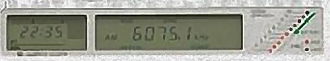
In 2011 the LCD and LED digit display technology is over 30 years old and VFD digit technology almost 50 years old. Perhaps with Domestic Radio the Alarm Clock radio sets got VFD, LED and LCD seven segment displays before they were used for frequency display. In 2011 a €2 non-PLL pocket AM/FM superhet can have frequency counter/clock combo chip for time, alarm and frequency on a four digit LCD with built in annunciators.
Glass and seal devleopment allowed a change from traditional Thermonic valve tube style envelopes to flat glass sheets in a planar assembly with lower labour and multple characters for Neon/Plasma (up to 640 x 480 panels for portable computing by early 1980s), VFD and LCD.
To Follow
- Neon / Gas filled display devices part II
- Various VFD devices
- LED, LCD and CRT Displays.
Related Articles
- Images of magic eye types and overview of types
- How the "Tune-A-Lite" works
- How the Magic Eye Works
- The Russian Neon/Argon Bargraph IN-13 (there is a less sensitive IN-9)
- The History of Tuning Indicators
- Indicators: Gas filled, Neon, Argon
To thank the Author because you find the post helpful or well done.
Vintage LED
The Production LED (Light Emitting Diode) dates from 1962.
LED History
The story is older. Henry Round, assistant to radio pioneer Marconi, was the first to discover that semiconductors could produce light perhaps about 1907.
Oleg Vladimirovich Losev in 1927 also independently discovered the LED and wrote a paper for a Russian Journal, later publishing in German and British Journals according to Nikolay Zheludev. Unfortunately Losev died of hunger in 1942 during the blockade of Leningrad, at the age of 39.In 1941 he had written a paper (now lost) on a semiconductor 3 terminal amplifying device. (Summary edited from Report in April 11, 2007 Newscientist)
The first LEDs were red and not very efficient. Soon there was also green. In 1973 I was assured by a Materials expert at college that the "band gap" needed for blue was not possible in any semiconductor so LED colour TV (OLED are "true" LEDs in this historic sense) was not possible unless maybe semiconductor diamond. Today we have Blue LEDs. Maybe too many of them!
Early LED were only separate indicator lamps. Bargraphs for signal or audio level simply used a number of separate LEDs.
Sony ICF2001D LED bargraph half lit (1985)
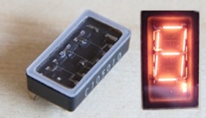
Though LCD panel used in a Watch from 1971, the earliest pocket calculators and Professional Receivers and Test Equipment using LED instead of Nixie, Dekatron, Planaplex (7 segement neon) or VFD used primitive 7 segment LEDs with few chips and limited diffusers to minimise loss of brightness.


1970s LED Frequency display with close up of one segment
(appears to be two chips each with 3 LEDs) This still works fine.

Early 1970s calculator display
(Very small digits with magnifying cover)
You can see why the VFD (single tube) in 1970s were more popular!
The Present
Today (2011) "light pipe" technology and improved semiconductors allows as few as three LED chips to light a larger segment brighter. All kinds of combinations of elements to make compound semiconductors allow almost monochromatic various Infra Red (invisible) Reds, Amber, Orange, Yellow, various Greens, Cyan, Blue, Far Blue/Violet and Violet/Near UV (visible) and even invisible long wave UV. White LEDs don't actually exist. They are Blue, Far Blue/Violet and Violet/Near UV (visible) with a few phosphors added to add Red and Yellow light. They are very much more discontinuous than Florescent or CFL lamps (they have short wave UV which works Phosphors better) usually particularly lacking in Cyan part of spectrum.
The 5 x 7 Dot matrix character panels, Message displays use multiple 5 x 7 panels or separate LEDs. Usually Red or Green. "Colour" LED is Red, Green and Blue chips in one package with clever diffuser/light pipe to mix the light. The large hall or outdoor colour screens use only RGB package for smaller displays. The larger Auditorium or hall LED screens use 3mm to 15mmm separate Red, Green and Blue LEDs arranged suitably. Larger panels may use nearly 8.3 million separate LEDs (football ground etc).
So called LED TVs apart from very small OLED or AMOLED are actually LED edge lit or back lit LCD panels. As of 2011 there are no domestic LED TVs.
LED seven segment displays are still common as the digits in a mains clock radio and frequency display on CB radio but otherwise LEDs like neon are mostly now relegated to Annunciators and illumination. Many portable devices use a single LED and light pipe to illuminate an entire LCD pane.
To thank the Author because you find the post helpful or well done.
CRT as an Indicator and Display
As well as the CRT (Cathode Ray Tube, Electron Beam or Gun or Braun Tube) familar as TV screen (now hardly made) there are less familar or "hidden" CRT devices
The miniature CRT: “Magic Eye”, “Cat's Eye”.
Direct or indirect heated cathode and 90V to 300V operation. Vary negative grid voltage. (1934 to 1965). They have about 1000hrs operational life. They gradually get dimmer usually rather than sudden failure.
- Usually triode, but may have multiple moving segments. Some may be more basic diode or more complex Pentode.
- Dual controls (i.e. Stereo audio levels) such as older 6AD6 (approximately 6AF6, 6355, R2164) and later EM83 (UM83), EMM801, EMM802,
- Three separately controlled bargraphs. The Octal top view 6AL7 (CV3707) and also side view EMM803.
- Rare electrostatic spot deflection type
Read more about Magic Eyes on these links.
- History of Tuning Indicators
- How the German Tuning indicators work
- Magic Eye Patterns
- Overview of Electronic Vintage Indicator Technology (no Meters or other Mechanical displays) which extends to numeric display of Frequency and simple Annunciators, not just Tuning Indicators.
- Neon Indicators including Tuneon list
- The Tune-A-Lite
- IN-13 Russian Bargraph for Signal Strength
- Lifetime of the Magic Eye
- Substitution of EM34
- Substitution of EM11
- Operation of the DM70 or DM71
Ordinary CRT as a display
The earliest use is as an oscilloscope or oscillograph to display waveforms (even pre-dates the triode). The CRT was invented (possibly separately) by Karl Ferdinand Braun and J.J. Thomson in 1897. It's likely the earliest models used cold cathode and thus had very low beam current.
A Dutch inventor made a CRT based version of the Baird 22 line mechanical TV before 1936 and Osram in 1934 published a design for CRT based silent replacement of Mechanical TV receiver.
Electronic TV (using CRT for camera and display) was proposed by A.A. Campbell-Swinton between 1905 and 1908, Manfred von Ardenne in 1923, Philo Farnsworth 1927, Vladimir Zworykin (between 1923 and 1929) who had the first practical camera at RCA. Isaac Shoenberg was the main expert in EMI also on Stereo in the 1930s. Also in the 1920s Kálmán Tihanyi worked on Electronic TV and Plasma (Like neon) display screen. Alan Blumlien proposed the UK 405 lines and was responsible also for HiFi disc cutting in 1930s. He died on a flight testing airborne radar during WWII (likely using CRT in the aircraft). WWII saw a big increase in CRT production for Radar displays. The German scientists developed fully electronic true HDTV for remote monitoring of Rocket ranges in 1940s and the Russians developed 625 line TV before 1948.
Lee De Forest's Triode was 1906 to 1907.
Oscilloscope
As well as test gear in its own right, the scope was also used to monitor the waveform or distortion of Radio transmitters, so Yaesu had the YO-901 adaptor (a scope) for FT101 and FT910 series radio sets.
Later connected to the Radio receiver IF was the panoramic adaptor or display, a simple dedicated "spectrum" analyser using a narrow swept IF, envelope/Peak AM detector and an integral scope.

Also search Panoramic on models. Not many yet have pictures
Raster based displays on Radio
Calculators, Cash registers and Radio Sets (not domestic though) have used miniature "regular" CRT.


IC-718 Transeiver and IC R9000E receiver
(about 5" or 125mm diagonal)
These Amateur and semi-professional Radio systems use a mechanical meter for signal level and use the CRT as panoramic Spectrum display, but with text and other information. They are Raster scan based.

Small CRT dedicated to 13 x 4 digits only
(Calculators and Cash Registers)
Stranger CRT based displays

 The Telefunken XM1000 is possibly what is called a Nimo tube, was a CRT (2,500V Anode!) but 10V switching to select one of 10 digits, left decimal or right decimal with the 12 control electrodes. The cathode ray numeric display tube XM 1000 is equipped with a flat quadrangular fluorescent screen, measuring approx. 27 mm by 20 mm, behind a front glass.
The BA0000P31 is another Nimo tube.
The Charactron is a similar kind of idea but much larger (Consolidated Vultee Aircraft Corporation) or Typotron (Hughes Aircraft Corporation). These date from the early 1950s and could be up to 19" (45cm). .

Charactron U.S. Patents 2,735,956 & 2,824,250
(image shared by Wikipedia and reformatted)
To thank the Author because you find the post helpful or well done.