Tube Socket Adapter Kit MX-949A/U
MILITARY U.S. (different makers for same model)
- Country
- United States of America (USA)
- Manufacturer / Brand
- MILITARY U.S. (different makers for same model)
- Year
- 1955 ??
- Category
- Service- or Lab Equipment
- Radiomuseum.org ID
- 150085


USA_Kit MX-949A/U

USA_Kit MX-949A/U_jpg
USA_Kit MX-949A/U_jpg


Click on the schematic thumbnail to request the schematic as a free document.
- Wave bands
- - without
- Power type and voltage
- Powered by external power supply or a main unit.
- Loudspeaker
- - - No sound reproduction output.
- Material
- Metal case
- from Radiomuseum.org
- Model: Tube Socket Adapter Kit MX-949A/U - MILITARY U.S. different makers
- Shape
- Tablemodel, with any shape - general.
- Dimensions (WHD)
- 270 x 95 x 225 mm / 10.6 x 3.7 x 8.9 inch
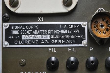
- Notes
- Socket expansion set for I-177 and TV-7 military tube testers.
Also manufactured in Europe by Lorenz.
- Source of data
- - - Manufacturers Literature
- Author
- Model page created by Emilio Ciardiello. See "Data change" for further contributors.
- Other Models
-
Here you find 408 models, 360 with images and 215 with schematics for wireless sets etc. In French: TSF for Télégraphie sans fil.
All listed radios etc. from MILITARY U.S. (different makers for same model)
Collections
The model Tube Socket Adapter Kit is part of the collections of the following members.
Forum contributions about this model: MILITARY U.S.: Tube Socket Adapter Kit MX-949A/U
Threads: 1 | Posts: 3
UPDATE YOUR HICKOK I-177 TO FALL 1971
with the data rollchart of model 6000
by Marco Gilardetti and Dale Spear
This article has been written in Italian language for Le Radio di Sophie (Italy) and in English language for the Radimuseum Stiftung Luzern (Switzerland). All rights reserved on text, pictures, software and all related attachments. Free use and copy if the article is correctly referenced; trading, sale or resell in every form is strictly prohibited. For a correct reference to this article: Gilardetti M., Spear D.: Update your Hickok I-177 to fall 1971 with the data rollchart of model 6000. The Web (leradiodisophie.it & radiomuseum.org); Italy - U.S.A. - Switzerland; July 2011 - February 2012.
Questo articolo puo' essere letto anche in lingua italiana su Le Radio di Sophie
INTRODUCTION
The purchase of a tube tester is an exciting step for a radio ham, but may have frustrating angles indeed. As a matter of fact, North-American instruments will not test European tubes while European units are harder to find and will test, in the best case, only the most diffused U.S. tubes. Moreover, older tube testers have a data chart necessarily limited to older tubes, while recent testers can test recent tubes but lack data belonging to old tubes, which are no longer reported on their charts. These tubes were back then considered “obsolete”, but today they may be of the greatest importance in the vintage radio repair hobby. Well-off persons usually buy more than one tube tester; all others get along as they can.
This problem is not new. The hope – or better the dream – is to be able to update a tube tester’s data chart by deducing values for newer tubes from a more recent instrument. This task has been faced in an interesting article [1] dated November 1964, in which the tube tester I-177 is updated by using the roll charts of the 6000 series models. The article relies mostly on one assumption: Hickok used basically the same circuit in the two testers, only adding a few new functions and improving the convenience and versatility of the new instrument. As it is well known, the famous Hickok dynamic tube test circuit was patented. It is a relatively simple, almost elementary circuit; however, in virtue of the patent, all competitors had to design different circuits, sometimes clever but not always as effective. Hickok, instead, had the opportunity to use its own circuit safe from competition, as it actually did by leaving it almost untouched for years and years.
Among all models produced by Hickok, Bradley considered the I-177 because in 1964, after having served the U.S. Army (as well as the N.A.T.O. allied forces) for over two decades, it was being massively dismissed on the tide of technical progress. It is estimated that approximately 40,000 I-177 units were produced, so there was a huge surplus of military tube testers, well used but often in perfect efficiency, for sale at bargain prices.
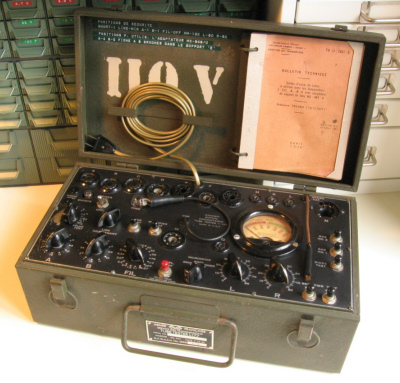
Figure 1 – The Hickok I-177 tube tester. This specific variant was made for
the Transmission Corps of the French Army.
(Photo: M. Gilardetti)
The big-hearted I-177 was then almost junk. Thus, Bradley designed a straightforward restyling of the tube tester, which irreversibly altered the hardware of the instrument. In few words a spare cover (to be taken from a second broken unit) had to be assembled over the original cover; then it had to be drilled for new sockets and potentiometers to be installed. Optionally, a true 6000 rollchart (which was then still available as a spare part from Hickok) could be fit in a slit. All old controls were not to be touched any longer, and in some cases it was suggested to physically remove the knobs.
This radical update has been made by one of the authors, and it is shown in image 2. However, under today prospects, the Hickok I-177 is no longer “junk” but instead a collectable instrument, which made the history of tube electronics, of the radio and of the army altogether; thus its alteration would be considered by most as absolutely unacceptable.

Figure 2 – A Hickok I-177 modified as suggested in Bradley’s article [1].
On the left, the second superimposed cover is clearly visible;
on the right, the new bank of sockets and switches can be seen.
The L and R knobs’ dial range has been converted to a 0-100 scale.
(Photo: D. Spear)
But this is a case in which “new technologies” may help “old technologies” by giving them new blood: electronic calculators today can do automated operations which were unthinkable in 1964. The authors have adapted by informatic means the data rollchart of 6000 series models to be directly used on the unmodified I-177, and in the next chapters it will be shown how to use this data through the MX-949/U expansion box, eventually to be built by those who don’t own one.
MATERIALS AND METHODS
Three data sources were used: the rollchart for tube testers model 6000, 6000A and 6005 code 3200-285, fall 1971 update; the supplementary test data table for obsolete tubes code 3200-166; and the supplementary test data table for foreign tubes (no code). The latter is of primary importance as it enables testing of many classic tubes with European codes, like the Rimlocks, for which the I-177 was so far useless. Together with the 1971 update, which incorporates also very recent tubes (like Compactrons, Decals and Nuvistors) it grants a huge data list: parameters for testing as much as 4,724 tubes are given.

Figure 3 – American Engineer’s sense of humour:
the data roll chart for obsolete tubes
is written... in gothic font!
The rollcharts were cut into strips of convenient length and optically scanned. The images were read by an automatic character recognition software (ABBYY FineReader) and visually inspected to fix the most evident errors. The data base so collected was submitted to a control, elaboration and conversion program [2] written in SAS™ (Statistical Analysis Software, engine v8) language. All parameters underwent to logical and arithmetic controls to reveal typos or read errors, or out of range values. When possible, errors were corrected automatically; the data base has been manually edited in all other cases.
At the end of the data check an informatics version of the rollchart for models 6000, 6000A and 6005 was ready. Although this was only a step towards the final goal, it has been nonetheless given out to the public in respect of its usefulness.
The data then underwent further elaboration to be directly used on the I-177. More in detail: the setting of selectors was translated in a sequence of wiring for the MX-949/U expansion box; the function selector setting was converted in the indication of the test button to be pressed on the I-177; the bias and shunt parameters, originally expressed on a 0-100 scale in the series 6000 roll chart, have been re-computed on a 0-80 scale to correspond with the I-177 potentiometer scales. Voltages or functions not available on the I-177 have been retrieved and marked out by added text in the notations field.
The data base, in order to make it easily accessible to the public, has been finally converted in files for Microsoft Office™ applications by means of the DBMS/copy™ translator. Although the correct format for data bases would be an Access™ file, the data chart is here published as an Excel™ spread sheet as we reckon this as the usual file format to deliver similar works on the web.
LIMITATIONS
The 6000 series rollcharts list both typos (like the non existing W position for the switch setting of the 6JC5 tube) as well as conceptual errors. In spite of the care put in both visual and automated controls, further errors may have occurred, particularly during the character recognition process. For these reasons the use of the tables is at your own risk; the authors decline any responsibility for accidents or damage due to errors or data included or missing in the tables.
The foreign data chart lists mainly tubes of international use, thus many European-specific models, like old German “cup” socket tubes, are not included.
The five test buttons of the I-177 (Ampl. Test; Rect. St’d; Diode Test; Test OZ4; Rectifier 117N7) are replaced on the 6000 series with a single test button in conjunction with an A to G function selector. Thus two functions, namely B and F, are new and have no correspondence on the I-177. It is likely that F function has the purpose of testing high voltage tubes like TV rectifiers, while B function delivers to screen grids a reduced 60V tension (135V being the standard test voltage). A limited group of mainly lesser tubes corresponds to F function; B function is instead used to test a broader group of tubes (295 overall) and has been deeply investigated. However, as a simple procedure to emulate B function on the I-177 has not been devised, both group of tubes will be impossible to test.
Some tube types – especially Nuvistors – are listed twice on the tables on two subsequent rows showing different test settings. This is due to subtle differences between the 6000 and 6000A models, which used specific adapters and procedures. In these cases, logics must be used to determine which of the two settings is the correct one for the tube being tested, comparing the pinout with the diagram on the tube charts (especially with Nuvistors with head cap connector). When possible, directions about which row reports the correct data to be used on the I-177 has been added to the notations field.
Finally, it should be kept in mind that 6000 series instruments have some sort of built-in ambiguity concerning the use of the head cap connector. It is, in few words, impossible to automatically distinguish tubes which need the cap connector from those with a grid connected to pin 10. The same applies for those tubes which have the plate connected to the top cap. This ambiguity has been recalled in the tables with settings written as G=10 (CAP) and P=10 (CAP). The final user will then determine, using good sense or, better yet, by checking on the tube’s pinout (now easily available on the internet), if the cap connector shall be used and for which electrode.
OUTCOMES’ RELIABILITY
The converted parameters have been tested with a group of tubes that were also listed on the I-177 original data chart: the instrument’s readings have been compared among each other, and also with readings of other test equipment.
Comparing the figures of the two set of parameters - the original and the converted ones - differences among the L and R settings can be frequently observed. This is partly expected, as the 6000 series instruments don’t have the 3000-6000-15000 µMHO switch: the same function is achieved by rotating the Shunt knob more clockwise. However, the readings on the good/replace scale have been in accordance with what is expected, that is, exhausted tubes have been marked as to be replaced while efficient tubes passed the test.
The mutual conductance readings in µMHO gave even more promising results: the values agreed very well with those reported in the Average Mutual Conductance column.
USE OF THE TABLES
THE MX-949/U EXPANSION BOX
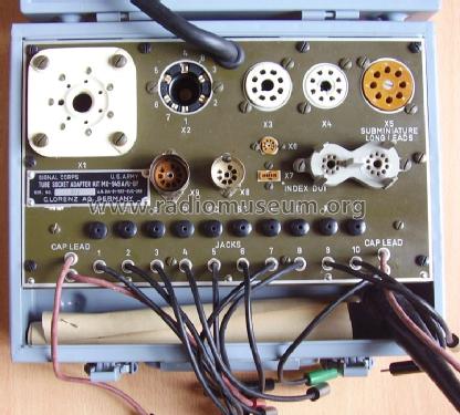
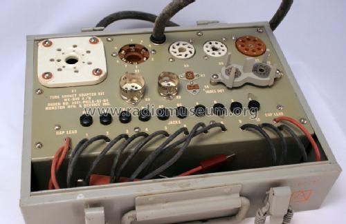
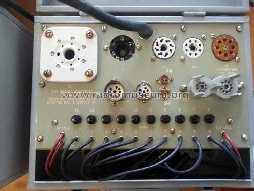
The 6000 series tube testers are extremely versatile: each electrode of the sockets leads to a rotary switch. With the bank of switches, it is then possible to arrange every pinout for every tube. On the I-177 instead, in order to speed up the setting, only two multi-way rotary switches (namely A and B) were installed. Quite obviously, with only two switches just a portion of all possible pinouts can be wired. To partly overcome this limitation, some socket types are repeated and hard-wired in different configurations (this is the case of the two Octal sockets E and G, and of the three miniature H, K and L). However, with the increase of tube models available, this scheme proved too limited. Hickok then provided the army with an expansion box named MX-949/U: it offered some extra sockets and also the possibility to freely set the pinout by a bank of jacks and receptacles. Understanding how the expansion box works is easy: it has to be connected to the I-177 by the Octal socket marked E. Once the A and B selectors are switched to a specific position (A=4 and B=2), the test voltages are univocally output to the bank of receptacles on the expansion box: two receptacles will provide cathode tension, two the control grid signal, two the plate high voltage, and two the filament current. Tensions are duplicated as in some cases they must be delivered to more than one electrode (as it is with cathode tension, which is used as well for suppression grid in penthodes). It is then sufficient to connect the correct plug in the correct receptacle to wire up the sockets as desired. Plugs are numbered 1 to 10 and each leads to the same-numbered contact on every socket: i.e. by connecting plug number 2 to K receptacle, the cathode tension is sent to every number 2 pin of all sockets. Plug number 10, however, is useless as it has no corresponding pin (note that all sockets on the expansion box have a maximum of 9 pins). Two extra plugs marked CAP lead directly to the pair of spring-loaded top cap connectors.
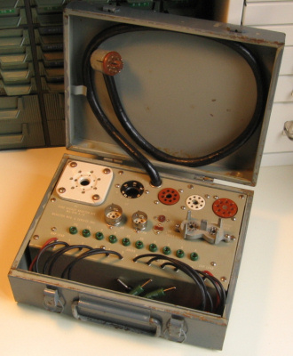
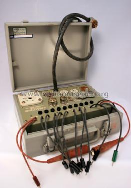
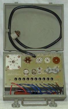
Figure 4 – The Hickok MX-949/U expansion box.
The bank of jacks and receptacles, with which
the pinout can be wired, is easily seen.
On the upper cover: the connection cable
terminated with an Octal plug
to be inserted into the I-177.
(Photo: M. Gilardetti)
Finding an I-177 for sale is not an easy task, but finding its expansion box companion is even harder. However, the expansion box can be easily made by DIYers, and it’s even cheaper. As a matter of fact, only some of the sockets are truly useful for the radio amateur: mainly Octal, Noval, miniature 7-pin and Rimlock; the most demanding can also be interested in Compactron, Decal and Nuvistor. By following the schematics [3] and keeping in mind this introduction, building the expansion box will be an amusing task.
DATA SORTING
Tubes are listed in strict alphabetical order and not, as often happens on paper charts, by filament tension or by function. It must then be remembered that tube 6V6 is listed after 12AT7, although the latter works at a higher filament voltage. For the same reason, Nuvistor 7586 precedes the classic 80 rectifier.
TUBE TEST ON THE REPLACE/GOOD SCALE
Before proceeding, check if the tube to be tested is listed on the original charts included in the I-177 instrument. If positive, it is advisable to use the original settings provided by Hickok.
Otherwise, connect the expansion box to the tube tester through the E connector and set A knob on 4, B knob on 2 and the scale selector on 3000 µMHO. Wire up the expansion box’ plugs and receptacles as suggested by the columns "fil", "grid", "plate", "screen", "cath" and "suppr". Whenever possible, always check the pinout on the tube’s technical papers, especially when the tube has the cap grid connector or has more than 9 pins. Then set Volt, L and R knobs to the specified values, turn the tube tester on, perform the usual shorts check sequence and finally press the specified test button. The answer will be given in the usual way on the red-green replace/good scale (or over the Diodes OK mark in case of diodes).
MUTUAL CONDUCTANCE MEASUREMENT IN µMHO
As already introduced, the 6000 series instruments don’t have the 3000-6000-15000 µMHO selector: the same task is performed by three calibrated dots marked on the Shunt dial, while the I-177 has one single calibrated dot (the Gm point, which replaces the figure 60 on L dial).
For this reason, the scale of the instrument must be determined by expectations. If the expected average mutual conductance is - say- 1200 µMHO, then the scale selector will be set at 3000; if the expected reading is instead 4500 µMHO, then it will be set at 6000.
To read the value, set the tube tester and expansion box as described for the replace/good test for the specific tube to be tested, except for knob L which must be set to Gm. By pressing the Ampl. Test button the galvanometer will give the reading (don’t forget to read it on the right scale).
The values given in the table’s Average Mutual Conductance column are those of a normal tube of mean usage; tubes in excellent efficiency conditions may be expected to give readings twice as high as those listed.
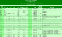
Table 1 – Rollchart for the tube tester Hickok model I-177,
computed from the rollcharts for the 6000 series instruments,
and rollchart for models 6000, 6000A and 6005.
REFERENCES
[1] Bradley W. T.: Updating the I-177 surplus tube tester. A modern checker at low cost. QST, November 1964.
[2] Gilardetti M.: Hickok 6000A - Hickok I-177 integrity check, clean up and tube chart conversion program written for SAS engine V8. Program list. © M. Gilardetti, Torino, October 2009.
[3] Hickok Electr. Instr. Co.: Signal Corps tube socket adapter kit MX-949\U for I-177 Army tube tester. Schematics.
Attachments
- Immagine 1 (86 KB)
- Immagine 2bis (60 KB)
- Immagine3 (22 KB)
- Immagine 4 (68 KB)
- Immagine 5 (37 KB)
- Hickok 6000-I177 program list.sas (54 KB)
- Gilardetti - Spear - Hickok I177 6000 rollchart a6 (1756 KB)
- Bradley, Updating the I-177, QST, Nov 1964 (4053 KB)
Marco Gilardetti, 17.Feb.12