90A Highboy Late
Philco, Philadelphia Stg. Batt. Co.; USA
- Pays
- Etats-Unis
- Fabricant / Marque
- Philco, Philadelphia Stg. Batt. Co.; USA
- Année
- 1932

- Catégorie
- Radio - ou tuner d'après la guerre 1939-45
- Radiomuseum.org ID
- 138520


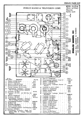


Scanned from the Philco Folder 2674.
Cliquez sur la vignette du schéma pour le demander en tant que document gratuit.
- No. de tubes
- 9
- Principe général
- Super hétérodyne avec étage HF; FI/IF 260 kHz
- Circuits accordés
- 6 Circuits MA (AM)
- Gammes d'ondes
- PO uniquement
- Tension / type courant
- Alimentation Courant Alternatif (CA) / 25 to 60 cycles, 115 Volt
- Haut-parleur
- HP dynamique à électro-aimant (électrodynamique)
- Matière
- Boitier en bois
- De Radiomuseum.org
- Modèle: 90A Highboy [Late] - Philco, Philadelphia Stg. Batt
- Forme
- Console avec pieds hauts > 50% de la hauteur
- Remarques
-
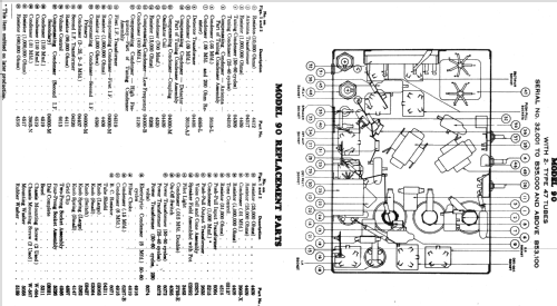
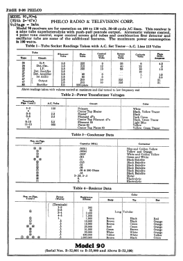
Models 90 and 90A were available in a cathedral, a lowboy, and a highboy cabinet. The chassis was made in three versions - an early model 90 and 90A with two 45 output tubes in push-pull, a middle version with one 47 output tube, and a late version with two 47 output tubes. Model 90 is for 115 VAC 50-60 Hz; model 90A is for 115 VAC 25-60 Hz.
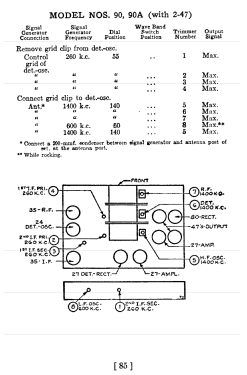
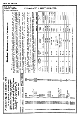
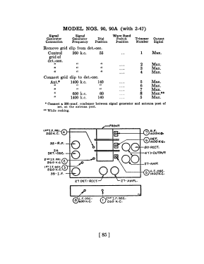
The models 90 and 90A "early" and "middle" have a 4-gang tuning condenser plus 3 tuned IF circuit - both with IF 175 (Rider's change note 8-3). The version "middle", which are above serial number 237,001, of the model 90 and 90A has tubes: 24 RF, 27 osc, 24 1st det., 24 IF, 27 2nd det. rect., 27 det. amp., 27 1st AF amp, 47 output and 80 rectifier. The "late" model 90 and 90A again have push-pull output but with 2 x 47 tubes. See Rider's Philco 3-35 for IF 260 kHz. Applied on models serial B-32001 to B-35000 and above B-53100. They have a 3-gang tuning condenser and only 6 tuned circuits. The same differences can be found for all cabinets, both 90 and 90A: Baby Grand (Cathedral), Lowboy and Highboy (with a stretcher).
The cathedral cabinet is the classic design by Edward L. Coombs, and is similar to the cathedral versions of model 21, 35, 46, and 70. [3331438-1133]
- Prix de mise sur le marché
- 109.00 $
- Source
- Philco Radio 1928-1942
- Source du schéma
- Rider's Perpetual, Volume 3 = 1933 and before
- Schémathèque (1)
- Philco 1928-36 Wiring Diagrams, Parts Lists, and Essential Service Data
- Schémathèque (3)
- Philco Folder 2674.
- Auteur
- Modèle crée par Thomas Albrecht. Voir les propositions de modification pour les contributeurs supplémentaires.
- D'autres Modèles
-
Vous pourrez trouver sous ce lien 4006 modèles d'appareils, 2205 avec des images et 3656 avec des schémas.
Tous les appareils de Philco, Philadelphia Stg. Batt. Co.; USA