Universal-Röhrenprüfgerät 247
Stuebler, K.H., Berlin
- Country
- Germany
- Manufacturer / Brand
- Stuebler, K.H., Berlin
- Year
- 1947/1948 ?
- Category
- Service- or Lab Equipment
- Radiomuseum.org ID
- 99719
-
- alternative name: Stübler; Ing. K.-H.

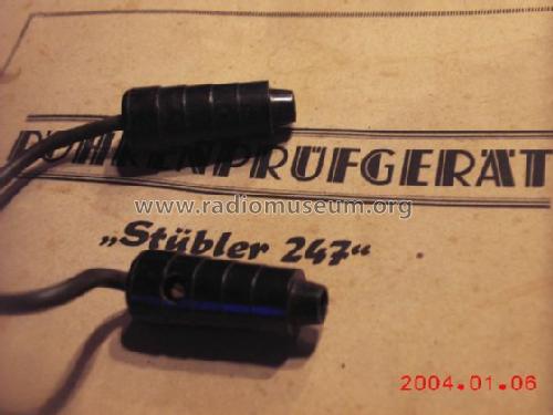
D_Stübler_"47_Brechkupplung
Click on the schematic thumbnail to request the schematic as a free document.
- Wave bands
- - without
- Power type and voltage
- Alternating Current supply (AC) / 220 Volt
- Loudspeaker
- - - No sound reproduction output.
- Material
- Leather / canvas / plastic - over other material
- from Radiomuseum.org
- Model: Universal-Röhrenprüfgerät 247 - Stuebler, K.H., Berlin
- Shape
- Tablemodel, with any shape - general.
- Dimensions (WHD)
- 350 x 270 x 190 mm / 13.8 x 10.6 x 7.5 inch
- Notes
-
Röhrenprüfgerät mit Wechselspannung als Testpotential, was durchaus eine brauchbare Messung des Anodenstroms und der Steilheit als Funktion der Betriebsbedingungen zulässt. Typisches "Nachkriegsgerät" mit professioneller Improvisation. Es ist z.Zt. unsicher, ob es sich um das Originalgehäuse handelt.
In der Beschreibung und Bedienungsanweisung steht: Das Röhrenprüfgerät "Stübler 247" ist eine Weiterentwicklung des Types Stübler "146W". Es können ca 1300 Röhren geprüft werden. (Die "Buchdruckerei Karl Pohle, Marienfelde", zeigt das Druckdatum August 1948)
- Net weight (2.2 lb = 1 kg)
- 4.7 kg / 10 lb 5.6 oz (10.352 lb)
- Literature/Schematics (1)
- -- Schematic
- Author
- Model page created by Albert Walenta. See "Data change" for further contributors.
- Other Models
-
Here you find 4 models, 3 with images and 2 with schematics for wireless sets etc. In French: TSF for Télégraphie sans fil.
All listed radios etc. from Stuebler, K.H., Berlin
Collections
The model Universal-Röhrenprüfgerät is part of the collections of the following members.
Forum contributions about this model: Stuebler, K.H.,: Universal-Röhrenprüfgerät 247
Threads: 2 | Posts: 3
Ich werde versuchen, die Bedienungsanleitung als Kopie zu erhalten und versuchen, das Foto zu übernehmen.
Reiner Scholz, 15.Aug.07
Text prepared for radiomuseum.org
TUBE TESTER
K. H. Stuebler*, Berlin, Germany
Model : ??? 1946?
__________________________________________________________________
* There are good reasons to assume that the unit has been built by Ing. K.H. Stuebler, Berlin. An almost similar tube tester is shown on the web page www.Oldradioworld.de (Wumpus´s old radio world), probably a later production (1947). The appearance, the layout, the switches and the contact bars are the same. Only the meter is different. It would be very useful if somebody could contribute some information on this company which certainly deserves to be mentioned in the "museum".
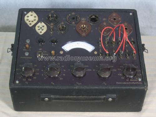
OVERVIEW
Transportable wooden case 350 mm x 270 mm x 190 mm, 5.6 kg
AC supply 220 V (internal change for 110 V)
10 sockets
11 heater voltages selectable
screen voltage selectable
anode voltage selectable
grid voltage (negative) selectable
test for short
measurement of anode current (now: 0…10 mA, 0…100 mA, original 6/60 mA)
test for vacuum
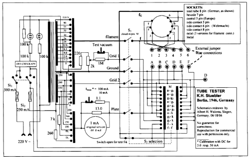
The evaluation of the quality of a tube is based on a measurement of the anode current as function of the grid voltage while the screen (in pentodes) is kept at a defined operational voltage. For simplicity the voltages are not rectified and therefore the measured current represents rather a mean value reflecting the characteristic Ia, Ua, Ug dependence. Since the tube acts as a valve and is conducting only in the positive half of the plate voltage the corresponding mean anode current is shown on the DC-meter. The grid voltage is applied with reversed polarity such that during the positive anode voltage period a negative grid is active. There will be a grid current during the positive grid voltage time but then the anode voltage is negative, hence there is no influence on the measured current. Although this current is obtained when the tube is run through an extended range of the Ua-Ug field it turns out to be quite close to the value one would obtain with a DC measurement at the setting given by the effective voltages. Therefore the tube tester allows the determination of the operating point in comparison to data tables at about 15% precision and with a precision of 20% the transconductance or the plate impedance.
The heater resistance and the inter - electrode isolation is checked with a gaseous conduction lamp and the 250 V output from the transformer. The vacuum test involves the observation of the increase of the anode current when at zero grid voltage a 1 MΩ resister is introduced into the grid connection.
The connectivity of individual tubes is matched by jumper cables connecting the voltage nodes of the electrodes to a numbered pin field. The match has to be looked up in a list or from a tube data manual.
In summary, the Stuebler tube tester allows a useful characterization of coarse tube failures and an astonishingly reliable determination of the tube characteristics.
PROCEDURES
The main switch (SL1 and SL2) has an intermediate position checking the test lamp ("Prüfanzeige") which later is used for inter-electrode resistance detection. In the second position this mode is disabled and all other operations take place. The main selection switch (S2) checks in sequence the inter electrode resistance. In the last position termed "Messen" (Measurement) the switch S1 connects the pins A to F with the corresponding potential as set by the rotating selectors and the heater voltage. At the same time the pin E and F are shortened which can be used to set the third grid (suppressor grid) to ground potential.
1) Connect the pins A to F with the corresponding socket pins numbered 1 to 6 using jumper wires with a special type of clip at the end. The numbering does not correspond to the usual sequence and has to be looked up from a list provided with the apparatus.
2) filament, screen and anode voltages are set to the values given in tube tables. For triodes only the anode and grid voltages are selected. For diodes the setting D1 for power rectifier tubes, D2 for others diodes is chosen.
3) S2 is rotated through the positions from left to right. In the first position the test lamp must glow since the conductivity of the filament is checked. The current is limited to 2 mA such that even sensitive battery powered tubes or the famous RV12 P2000 can be tested without causing damage. In the following positions the permutations of the electrodes are tested. A resistance < 100 kΩ is safely detected.
4) In the last position "Messen" (measurement) the filament voltage is connected to the socket pins and the other voltages are applied. When the tube starts to emit current this is measured on the meter in the anode circuit which is set to the default range of 100 mA. Pushing the button 10 mA changes the range correspondingly. Changing the grid voltage (range 0…20 V) shows the characteristics of the tube. The phase of this AC voltage (the effective voltage is indicated on the scale) is such that the polarity is opposed to the anode. Hence it operates as if a negative voltage is applied to the grid.
d) Vacuum: the grid voltage is set to zero and pushing the vacuum button should not change considerably the anode current otherwise positive ions are present indication a bad vacuum. If the grid voltage is not set to zero the anode current always will increase considerably since the introduced 1 MΩ resistor causes a phase shift of the AC voltage, such that a positive fraction coincides with the positive anode voltage. Clearly, this will increase the current irrespectively of vacuum condition.
Albert Walenta, 04.Jul.06