Analog Computers: RCA Typhoon, 1951
Analog Computers: RCA Typhoon, 1951

Analog computers were used to solve sets of generic simultaneous differential equations, to compute trigonometric functions, to perform coordinate transformations, multiplication, integration and similar tasks in real time. These computers used analog building blocks, as integrators, summing amplifiers, logarithmic amplifiers, function generators, and electromechanical sensors, actuators or displays. Analog computers offered several advantages over digital ones: they were faster, simpler, lighter and more reliable. Their limit was in the moderate accuracy, 0.5% or less, usually obtainable. Many analog computers were small dedicated equipment, often almost entirely electro-mechanic, with synchro repeaters, cams, potentiometers, differential gears and just some electronic error amplifiers, designed to accomplish a specific function, i.e. the position and the course computation in a navigation system. Here an example of an air-data analog computer.

Larger computers were designed for the study and the simulation of generic n-variable systems and their dimensions became impressive when complex problems had to be investigated, with the simultaneous handling of many variables. These computers had a number of operational amplifiers, some additional building blocks and one or more programming boards. The transfer functions to be simulated were programmed connecting the building blocks as required by plugging wires on the programming boards and setting the required parameters. Analog computers were widely used in the past, and some were also sold in kit form, as Heathkit EC-1 or ES-400 series.
With its 4000 vacuum tubes, RCA Typhoon was one of the largest analog computer ever built. Entered in service early in 1951, after three years of research and development under the direction of Arthur W. Vance, it had been intended for the investigation of complex problems, such as the evaluation of the performances of ships, planes and submarines, up to the design of complete guided missile systems. A staff of nine engineers and mathematicians plus six technicians was required to operate the computer. The problem was set up on approximately 100 dials and 6,000 plug-in connections on the programming switchboards. Output devices included two Electronic Associates Variplotter units and 18 GE photoelectric recording voltmeters, plus a three-dimensional trajectory indicator.
.jpg)
Picture of the operation control room with the control console and two plotting boards. Some of the computing racks are visible in the background. Below, Arthur W. Vance, head of the RCA Computer Section, at the control console.

The Typhoon computer included some 450 precision DC amplifiers and 20 computing servo units with multipliers, plus a large number of other components, as a bank of polystyrene capacitors that made possible up to 80 simultaneous integrations. The circuits were mounted in 43 racks, each 9 feet high; three racks were double standard width, 36 inches. Total power required was 46 kilowatts.
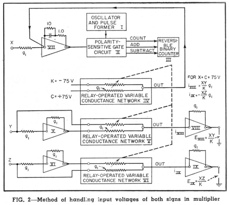
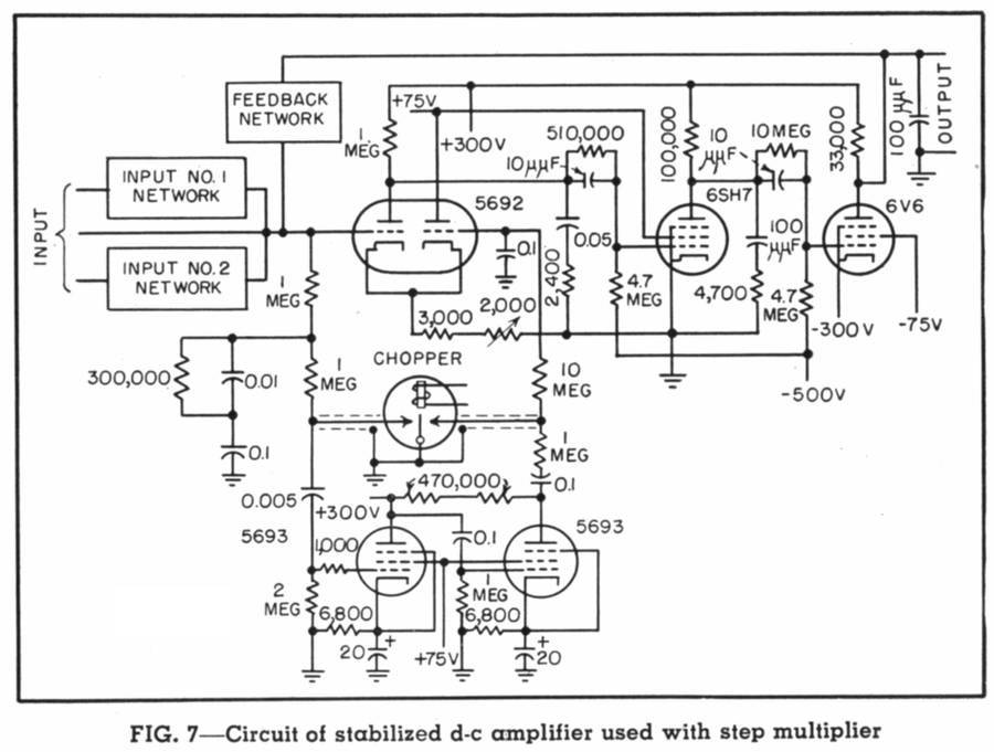
Hybrid step multipliers were included for fast coordinate conversions. Special circuits and components had to be developed to achieve a precision within 0.001% of full-scale. Very fast relays, capable of switching in 0.1 millisecond with no bounce were developed for the DAC sections. For maximum speed relay coils were driven by circuits with three 807s in parallel. Just few years later, simple inverted connection transistors should have performed the same function. Hybrid multipliers, using the above DACs, were capable to change from zero to full scale in 1 second. A simplified block diagram and the diagram of a DC stabilized amplifier are given. Here is a picture of the multiplier units. In foreground the three-dimensional servo-controlled trajectory indicator.

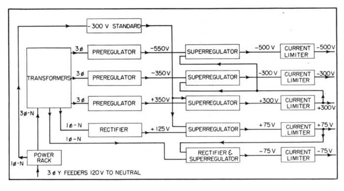
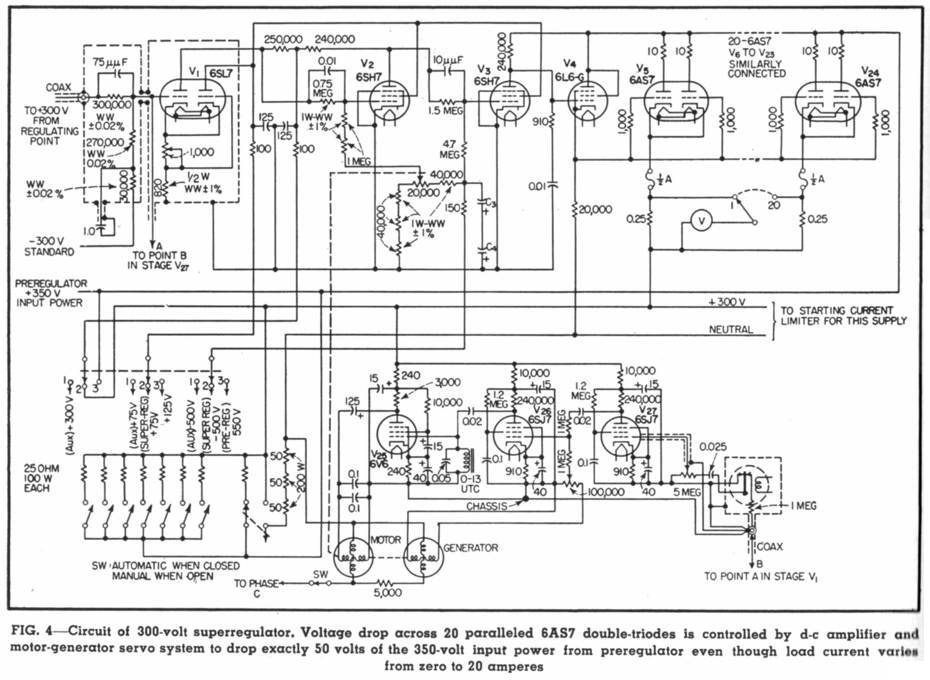
The stabilized power supply section occupied ten racks. Plate supplies generated +300 and –300V, each at 20A, regulated to 0.001-percent. Bias supplies gave +/-75V at 6A and –500V at 3A. The +/-300V and the -500V power supplies included thyratron preregulators, followed by superregulator sections, each using twenty 6AS7 twin triodes. The coarse voltage drop on the series pass regulators was kept to 50V by the preregulators. Picture below shows the entire supply section.

Sources: ‘Electronics’, February, April, August and December 1951.
To thank the Author because you find the post helpful or well done.