grundig: 51GW Gloria repairs and lessons learned
grundig: 51GW Gloria repairs and lessons learned

Fellow radiophiles,
A couple of weeks ago I hit the jackpot in my wish-list for radios. I found a Grundig Gloria 51GW on American ebay at #260646973478. This radio is not common on German ebay, and this may very well be the first time it has appeared in the USA. The seller "goodbycitylife" accepted my informal buy-it-now offer of $125, and the transaction was concluded without any trouble. Should you consider buying from this seller, I recommend him.
According to the seller, this radio came from a flea market in the heart of rural Pennsylvania, an area which has a large population with German roots. This radio was not exported to the USA. Perhaps an American soldier stationed in Germany brougth it back in the 1950's.
Repairs
 The radio was in very fine shape. The electrical repairs were straight-forward.
1- Electrolytic caps 4uF, 4uF&2uF. The power supply capacitors reformed with a gentle application of external voltage.
2-Two of the paper capacitors were objectionably leaky. One was the 50nF G2 bypass, and the other was the 10nF audio coupling cap to the output tube grid. The paper caps still had the correct capacitance, but too much leakage, so I simply wired a 0.22uF X7R 250V (TDK# FK20X7R2E224K) ceramic cap in series with the 50nF paper cap and a 0.047uF X7R 250V (TDK# FK20X7R2E473K) ceramic cap in series with the 10nF paper coupling cap. These ceramic caps are so tiny that the original caps don't have to be moved, thus helping preserve the history abd appearance of the radio. If the 10nF cap leakage drops to 1Meg, which is equal to the grid network impedance of the output tube, there will be more bass coupling than desired into the reed speaker. One alternative cap to solve this problem would be to wire a 10nF ceramic cap on the grid side, while shorting out the leaky cap and leaving it in place. Leaving the old paper cap wired to the plate side is less likely to pick up hum, than leaving it wired to the grid side.
 3-Lastly, the main 2.6kΩ ballast wire-wound resistor had two partially unraveled sections. I removed the resistor by untwisting the metal tab under the polystyrene chassis. Then unwound the loose nichrome wire from the first section on to a empty plastic pill bottle. Then rewound the wire on the pill bottle back on to the ceramic core of the resistor, taking care not to cross turns or kink the wire. The loose end of the NiCr wire was wrapped and crimped onto the original tab. I repeated this process for the other section. This was the tedious part of the repair, taking me about one hour to rewind each section.
Powering up the radio
The Gloria is a direct descendant of the famous DKE "Deutscher Klein Empfänger" series of radios that started manufacturing in the early 1930's. One nickname for this type of radio was the "Heinzelmann".
One of the features that it incorporates is the ability to operate from AC or DC power and at several voltage levels which, in this case, include 115V, 150V and 220V. While the radio will operate at any of these voltages, provided the proper tap is selected in the 2.6kΩ ballast resistor, the performance is significantly reduced at 115VAC that is available in the USA. The ballast resistor only adjusts the heater voltage for the VEL11 which is thus kept at 90V AC or DC. All the other voltages in the radio are derived directly from the power line with the selenium rectifier.
 The voltage and current levels under 115V operation are about half the value as compared to operation at 220V. This causes a reduction in sensitivity and maximum output power. The reed in the speaker is also out of alignment at 115V because only about half the current flows through it's coil. This makes the reed speaker looses sensitivity and distorts more.
 My solution to this problem was to make a simple lossy doubler power supply based on a 117Z6GT dual rectifier. This tube has just enough current capacity to run the 68mA load of the Gloria at 230VDC. The simple lossy doubler topology uses a 50uF 160V general purpose electrolytic input cap and a 120uF 330V disposable camera electrolytic flash capacitor. Flash capacitors are very compact, but are not made for large ripple currents. The modest 125mArms ripple current on this cap has not been a problem. The 50uF input cap should be no larger than rated 40uF rated load capacitance for the 117Z6, but I felt it was OK to go 25% over this recommendation and use the 50uF because I don't plan to use this radio continuously. Refer to the schematic and simulated LTSPICEIV waveforms for operational details.
This type of 220VDC supply should work very well for earlier DKE or Heinzelmann radios that will be operated at 117VAC in the USA. But keep in mind that the output voltage is a function of the load resistance presented by the radio. Under no-load conditions, the output voltage rises to 320VDC. When the radio is plugged back in, the voltage drops rapidly back down to 220VDC, without any damage to the radio.
If more load current is needed to maintain the 220VDC output, then the input capacitance can be increased. Reducing the output capacitance can be used for fine adjustment of the output voltage, but with more output ripple.
Another advantage of this type of DC supply, is that any residual hum is eliminated from the radio. DC operation also puts the least strain on the selenium rectifier by reducing it's RMS current to a minimum. This makes it possible to keep the original selenium rectifier in the radio, even if the reverse leakage has become excessive for AC operation. The 10nF capacitor in parallel with the selenium rectifier now may also be left intact, even if it is leaky, because it sees only the forward drop of the selenium rectifier.
Inductance measurements

 This radio was designed at the end of cycle of single tuned circuit regenerative radio designs. As such, it embodies over 20 years of lessons that were learned. I have been impressed the the sound quality and overall performance of the radio. This made me want to measure the various inductors that are at the heart of this performance. The two photos show the coil and it's connections to the tuning and regeneration capacitors.
 I used a mirror to capture details of the variable capacitors that are very cleverly housed in front of the speaker.
I annotated the inductance values and non-resonant voltage coupling ratios in the following schematic, which was originally scanned by Walter Wiesmüller. These values can serve for comparison with other designs, or even to run linear AC simulations.

 Note the three tap input coil with three choices of loading inductance: A3=515uH A2=40uH and A1=10uH. The highest impedance tap is A3, and should be used with short antennas of several feet. The A1 tap is for full size outdoor antennas, and A2 is for in-between sizes. Another effect to keep in mind is that the A3 input has the strongest loading effect on regeneration. This is evident when regeneration is adjusted to avoid oscillation with the antenna at A3, but starts oscillating and requires a reduction in regeneration if the antenna is moved to A2.
Another interesting feature is the Foil antenna that is taped inside the upper half of the case. This Foil also serves as a heat shield for the 2.6K ballast resistor and the VEL11 tube.
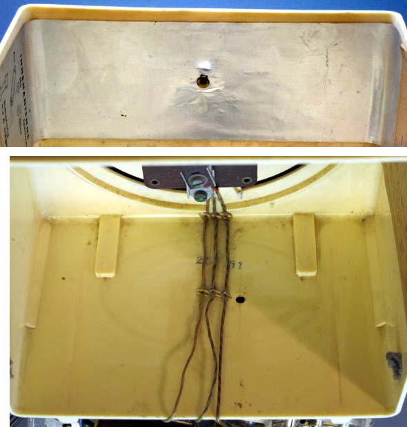 But the schematic suggests two ways to use this Foil antenna. If the antenna is connected directly to the main tuned circuit it will work as a small electric field antenna for strong local stations.
The second, and more ingenious, use of the foil antenna is to work with an optional parallel tank circuit wired between the foil and the main tuned circuit to serve as a local strong station trap. This is the "sperrkreis", or blocking circuit. There is a notched hole at the top center of the chassis, to mount the optional tank circuit. This hole seems sized to accept a coil form that is the same size as the main tuning coil shown above.
My Gloria did not come with this option, so I improvised one with a variable 635-78uH inductor in parallel with a 100pF capacitor shown in the photo. Note that the schematic is clear about the use of a fixed capacitance and variable inductance. This makes sense because the purpose of the circuit tuning is to change the frequency. A variable capacitance would vary the capacitive coupling in addition to the frequency.
 The operation of the notch filter with the foil antenna is based on the principle that the foil antenna and the external antenna are in phase, thus forcing the opposite canceling phase to the top of the main tuning circuit. Keep in mind that bringing your hand near the foil upsets the cancellation balance.
I tested the option in the 3rd floor of my wood framed house, where reception for the local station is strongest. I was able to substantially null out the local station at 1400kHz by tuning the tank circuit. This eliminated all leakage of the station to other dial locations, while still leaving plenty of signal to receive at 1400kHz. The input antenna connection is important for this scheme to work. I used the middle A2 connection for best cancellation of the strong local 1400kHz signal. I also limited the lenght of the antenna to 10 feet. Reception on the other stations was still good.
Connecting my 100 foot attic antenna to the lowest impedance tap at A1 injected more strong local 1400kHz signal than could be cancelled. Perhaps wiring my 10 foot wire to the foil to increase the cancelling signal might have made the notch work even with the attic antenna.
Homodyne Reception
One of operational tricks I have come to enjoy with regenerative receivers is Homodyne Reception with synchronous detection. This is done by advancing the regeneration control past the oscillation point, and then very carefully adjusting the tuning to obtain a lock to the carrier of the incoming signal. The frequency locking works best with stronger signals, as they can more easily force the oscillation frequency when they interact with the non-linear effects of detection on the resonant frequency. I first tried this trick with my Crosley 51. The advantage of Homodyne Reception is improved fidelity at the loss of some signal amplitude. The sound is very nice this way, with improved treble response.
Grid Leak Detection
 For some time, now I have had an interest in the mysteries of grid leak detection. I learned a number of lessons recently with my Philco 80Jr, and decided to put the Gloria through similar testing for comparison.
The photo shows the Gloria operating at 239V from the voltage doubler, which was connected to an isolation transformer during measurements.
The grid cap is removed, and a low leakage film capacitor bypasses the grid to ground to kill injected hum at the speaker.
The voltage source at the top of the photo supplied grid voltage from 0V to -1V in -100mV decrements and also measured at -2V, -3V and -4V.
 A Keithley 197 DVM and Fluke 87III were wired between the voltage source and the grid to measure the grid currents. The Keithley has 1kΩ of internal resistance and the Fluke has 100Ω of internal resistance in the uA scales. The Fluke was best to measure the 80uA current at 0V grid bias, while the Keithley was sensitive enough to pickup the -4pA leakage at -4V.
 The plots include corrections for the shunt resistance of the uAmmeters.
The first plot highlighs screen grid operation durig the measurements.
The adjacent plot shows the exponential nature of the diode conduction between 0V and -1V. Also note the very low -4pA leakage at -4V. This suggests a much harder vacuum than was present in the 36 tetrode in my Philco 80B Jr.

This plot shows a fairly good curve fit for grid current as a function of an exponential of the applied voltage.
This clearly points out that the familiar 1.5 root law of conduction for thermionic diodes does not apply at these very low current levels.
Also note that the internal grid resistance Rg1 is a strong function of bias current. It is this bias current that is programmed when a value for the external 2MegΩ resistor is chosen.
 This plot shows the intersection point of the 2Meg grid leak resistor load line with the grid current curve. This intersection occurs at 330uA and -650mV, and the grid resistance is 330kΩ at this current level.
This relatively high impedance seems close to the tuned tank circuit impedance because injection additional bias voltage externally through a 10Meg resistor, away from -0.65V did not improve reception noticeably, as it did in my experimentation with the Philco 80B Jr.
A quick calculation of the main resonant circuit impedance yields values that are well suited for loading by the 330KΩ internal Grid resistance:
L=168uH and Q=28 at 173kHz. At 1MHz, Q=28*1000/173=161. The apparent internal resistive impedance of the tank circuit at 1MHz is simply the product of the Inductive reactance XL=L*F*2π=1kΩ times the Q. With resonance at 1MHz, R=1kΩ*161=161kΩ. At 500kHz resonance, R=42kΩ, and at 1.5MHz resonance,R=384kΩ.
This range of tank circuit resistance from 42kΩ to 384kΩ at resonance is only a coarse estimate from the inductance and Q measurement I made with the Rohde&Schwarz BN6100. The real Q in the AM band may differ because of different losses at the 173kHz measurement frequency.
After seeing such low -4pA leakage with -4V at the detector grid, I measured the leakage at the output tetrode control grid around -50pA at -5.5V. This is a very low number for an output tube, but not surprising because both tubes share the same vacuum.
Reed Speaker


 One of the pleasant surprises of this radio was the nice sound that the reed speaker reproduced, without any shortage of bass. The design is a classic free edge with a balanced reed armature and permanent magnet. The free edge is lined with a velvet strip that gently rests the cone against the case. This partial seal against the case extends the low frequency response. The cone is much stiffer than a standard moving coil speaker. The cone is attached to the reed at a soldered slot on a metal button on the vibrating reed. The solder retains the cone, while allowing for some self-adjustment of the cone as it pivots slightly up or down when the cone is fitted against the case.
The reed rests in a pulled back position when power is off, to be moved forward by the plate current of the output tube during normal operation. See reed position above.
A few more detailed views


The following schematic was glued inside the case:

Best regards,
-Joe
To thank the Author because you find the post helpful or well done.
Main coil Q
Fellow radiophiles,
The quality, or Q factor, of the main tuned circuit is a critical parameter in the design of the regenerative detector. Two design goals are affected by the Q of the main coil. One is the bandwidth of the received signal and the other is the detection efficiency.
Detection efficiency, or the ability to convert the audio modulation into an audio signal, is drops rapidly for weak signals. Weak signals can be classified as signals that are less than 75mVp-p, which is the voltage swing that it takes to change grid conduction by a factor of 2, as measured in the previous post.
But weak signal detection can be easily remedied with positive (regenerative) feedback to increase the signal amplitude at the grid for detection. We can easily apply enough regeneration to increase the signal by 10x, or perhaps by 100x, with a very steady hand. In the 10x case, 10% more regeneration will cause oscillation, and in the 100x case, 1% more regeneration will cause oscillation. The 100x case is what it takes to make a 1mV signal detectable at the grid, after it has been regenerated 100x.
But high regeneration also comes with a price, and that is bandwidth reduction. If we start with a Q of 100 at 1MHz, which yields a 10kHz RF bandwidth and a detected 5kHz audio bandwidth, we will end up with a greatly reduced bandwidth. This makes the case for limited Q for adequate bandwidth before we apply regeneration. If we were receiving morse code which has very limited bandwidth, we would want the highest Q possible circuit before applying regeneration, but when receiving audio, bandwidth requirements become an important constraint.
This reasoning made me curious about the actual Q of the main tuning coil over the tuning range. I measured the Q with two different methods to gain confidence in my measurement.
My original posted measurement with the Rohde&Schwarz BN6100 gave me Q=28 at 173kHz while the inductor was resonated with the internal 5000pF reference capacitor. As my following alternative measurements show, it appears that my BN6100 is measuring Q about 30% low at this frequency.
The following measurements were all done with the radio power off.
First, I applied a calibrated sweep around the resonant frequency and took note of the -3dB RF Bandwidth. The Q is the ration of the Resonant frequency Fo to the RF bandwidth Q=Fo/RFBW. I injected the signal from a 50Ω generator to the lowest impedance tap A1 in the antenna coil with respect to the ground end of the same coil. There was slight loading effect from the 50Ω source impedance, as compared with driving the A1 tap with an additional 1kΩ.
Second I carefully adjusted a fixed frequency to obtain a peak resonant response, and then found what resistance value would cut the voltage at resonance in half. This resistance value matches the internal equivalent parallel resistance of the tank circuit at resonance. The Q is the ratio of this resistance to the identical reactance magnitudes of the capacitor or inductor at resonance. Q=Rparallel/XL=Rparallel/XL
| Q from frequency sweep | Q from resistive loading at resonance | ||||
| Fo | RFBW | Q=Fo/RFBW | Rparallel | XC=XL | Q=R/X |
| 173kHz | 4kHz | 43 | 7kΩ | 182Ω | 38 |
| 500kHz | 8kHz | 62 | 40kΩ | 527Ω | 75 |
| 1000kHz | 14kHz | 71 | 100kΩ | 1kΩ | 100 |
| 1600kHz | 32kHz | 50 | 130kΩ | 1.7kΩ | 76 |
This table shows a moderate Q for the main tuning coil over the tuning range, and Q~40 at the 173kHz test frequency used by the R&S BN6100, which is higher than the Q=28 given by the BN6100. The accuracy of the frequency sweep at 1000kHz and 1600kHz was probably somewhat compromised by the resolution of my reading.
Another result from these measurements is that tank circuit impedance between 40kΩ and 130kΩ is less than a third of the 330kΩ impedance of the grid, which was measured above. This means that the detection efficiency will not be optimal when all regeneration is eliminated.
Regeneration will increase the tank circuit impedance well past the 330kΩ grid impedance. When enough regeneration is applied to double the voltage at the tank signal, the apparent impedance of the tank circuit should quadruple in a relationship that is analogous to voltage and impedance transformation in a transformer. This suggests that optimum detection efficiency occurs when enough regeneration is applied to double the signal present at the tank, so the tank impedance approximately matches the grid impedance at 330kΩ.
All these measurement results suggest that the operating point and design values for this radio were well centered to cover a wide range of conflicting performance goals.
Further material is welcomed to extend this topic, in particular, any links to the German side of the Forum, where I have trouble knowing what to search for.
Best regards,
-Joe
To thank the Author because you find the post helpful or well done.
Further Material on LC Circuits and their Q

Further material on LC circuits and their Q can be found in a German text:
"Warum kann ein Radio mit einem Schwingkreis Sender trennen?"
"Why is it possible to tune in broadcast transmissions with a set which only has one circuit?"
Here some analysis and curves of LC circuits with and without reaction is presented.
It is shown that the Q of the LC circuit itself is not changed due to reaction. An audion with reaction is treated as a control circuit with positive feedback. Feedback does not affect the features of the LC circuit itself, albeit it changes the transfer function of the audion. But because only two energy storages (L & C) are within the feedback loop, the shape of the resonance curve remains unaffected by reaction.
In a practical case this means reaction can (nearly) not improve the far off selectivity of an audion. This can be realized if in a clear channel (without any transmission inside) the reaction is made stronger. An adjacent interferer will not become more quiet.
On the other hand, if a transmission is in the channel it will become detected louder if reaction is made stronger. So the ratio of the wanted signal to the unwanted signal of the adjacent interferer will raise. Therefore the impression is then that the selectivity has improved.
These effects easily can be verified with the aid of an audion receiver.
Regards,
Dietmar
To thank the Author because you find the post helpful or well done.