crosley: Homodyne loop reception, new case.
crosley: Homodyne loop reception, new case.

Hello fellow Radiophiles,
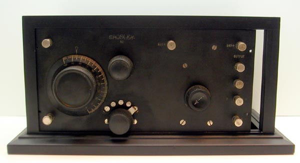
Last week I picked up a cute Crosley 51. It had no case and needed a few repairs.
First off, the rheostat had a few open turns on the hidden side of the resistor wire. I removed the rheostat, cleaned the NiCr wires gently with a soft sand paper, and resoldered the wires. NiCr wire takes well to solder.
The set screw for the main knob is a standard sloted screw, but it's head broke off long ago, and the knob slipped. While attempting to drill out the remainder of the screw, the screw stub screwed itself right out, so I simply replaced it with a new half inch 6/32 screw.
The grid-leak resistor was open, so I hid a 1Meg resistor under the grid leak resistor, in the same socket. This value seemed to work well in my experiments.
I did most of the cleaning with glass cleaner and DeOxit on the wires and metal parts. DeOxit is a contact cleaner, but also works well as a metal cleaner.
Tubes
I have a couple of 201A's that work in this set, but one is already in use in another set. So I decided to try some of the substitutes I built in the past.
I settled on this combination for use with a 3V "A" filament battery:
 For the detector I used the DM160 with a light bulb in series with the positive end of the filament. The light bulb measures 20 Ohms cold and drops 1.8V of the external 3V "A" battery. Changing the Filament/bulb sequence changes the grid bias by 1.8V. Either configuration functions in the detector, but the higher bias current afforded by having he filament on the negative end of the "A" battery gave a more sensitive detection. The grid leak resistor is returned to the positive end of the "A" Battery.
For the Audio amplifier, I used a CK5676 triode with a #46 bulb (rated 250mA at 6.3V) in series with the negative end of the filament. Here, it is very important to place the bulb on the negative end of the 3V "A" supply, to give the cathode about 1.5V of of equivalent C bias. This variant of the Crosley 51 has the C terminal wired to the A- terminal, so the C bias is zero volts, except for the added 1.5V at the filament. Without this 1.5V bias, the audio signal gets limited or attenuated by grid conduction at the Audio tube. My tests showed up to 3V p-p at the grid from a local station, so the 1.5V bias was just enough to avoid conduction on the positive peaks.
The 1.5V bulb drop in series with the negative end of the filament raises the entire filament by 1.5V, which is the equivalent to lowering the grid by -1.5V. One think to keep in mind is that the audio socket filament is wired backwards with respect to the labels on the socket. The + terminal in the socket goes to the A-minus supply.
Case

I got very lucky finding a suitable case. I wanted a case that would show inside the radio. I found a ready-made display case that was just the right size. Click to enlarge the thumbnail on the left to see measurement details for the case. The built-in mirrored back also helps show the tubes and circuitry. It cost around $30USD.
I broke and removed the front glass and cleared the tracks that held the glass to hold the radio. A pcb strip in the bottom track pushes up the radio to catch the top track. The left side track offers the best support.
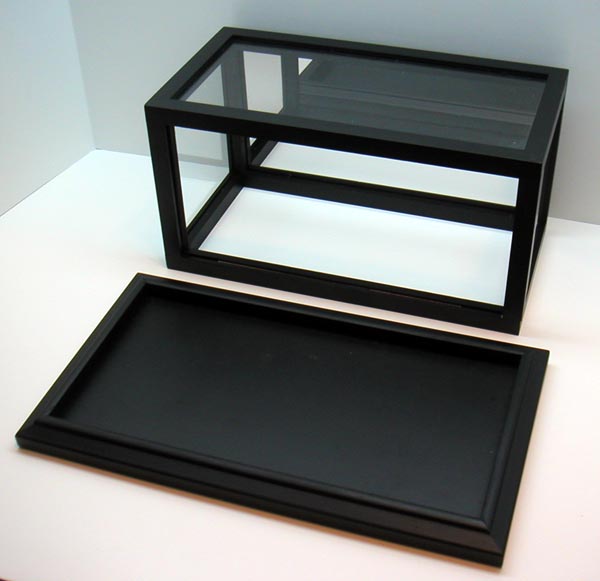
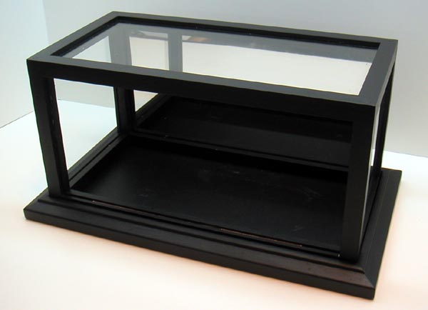

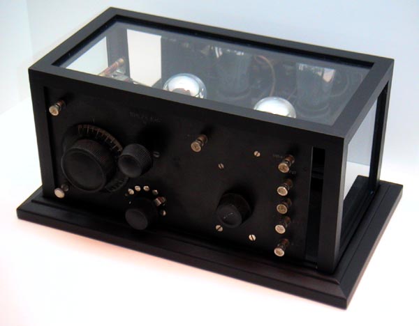


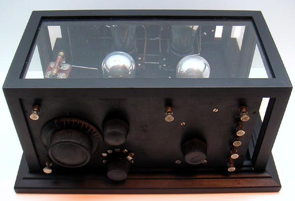
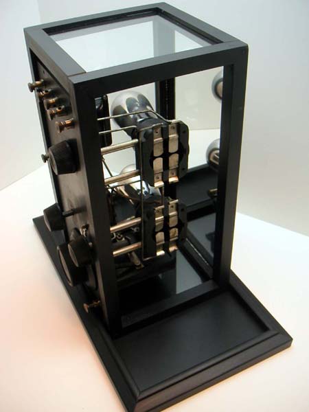
The top and bottom sections of the display case are separate pieces that make it easy to inspect the bottom of the radio.
 This photo shows the substitute tubes lit up. Note the green glow of the DM160 and the incandescent glow of the #46 bulb in series with the CK5676.
Operation

I conduted my tests with this setup. It comprises two D-cells for the 3V "A" battery, 6 NiMH rechargeable 9V batteries for the B+ 45V supply, with a tap at 22.5V for the detector. The actual voltage for each NiMH battery is 7.5V, not 9V. Check this post for more about battery packs.
There is also a 25k:4_Ohm transformer shown on the right for use with my modern set of head phones to judge radio sound quality independently of the the resonances of the period earphones.
The loop
The red and black leads on the left are wired to an external loop antenna. This antenna has 10 turns of wire over a 13 inch square form and has 86uH of inductance.
The series tuned LC circuit in the Crosley 51 works equally well with external wire antennas, or with loops. Loops have the potential for more selectivity and are more convenient to use than long wire antennas.
Parallel tuned input circuits, need a switching scheme to use the internal coil for external wire antenna, or disconnect the internal coil for use with an external loop.
The variable capacitor and variable coil give a lot of tuning flexibility for external antennas. Just about any loop of any inductance can be tuned by this set. I found this set quite easy to tune. Each of the coil taps overlaps the band coverage by about 50%.
The tickler coil inductance is 81uH with a Q=40 at 1MHz. The following table shows tap inductance as the tap switch is rotated clockwise, from left to right.
| tap | uH | Q at 1MHz |
|---|---|---|
| 1 | 56 | 23*1MHz/300kHz=77 |
| 2 | 171 |
29*1MHz/172kHz=169 |
| 3 | 305 | 32*1MHz/129kHz=248 |
| 4 | 434 | 30*1MHz/108kHz=278 |
| 5 | 530 | 28*1MHz/98kHz=286 |
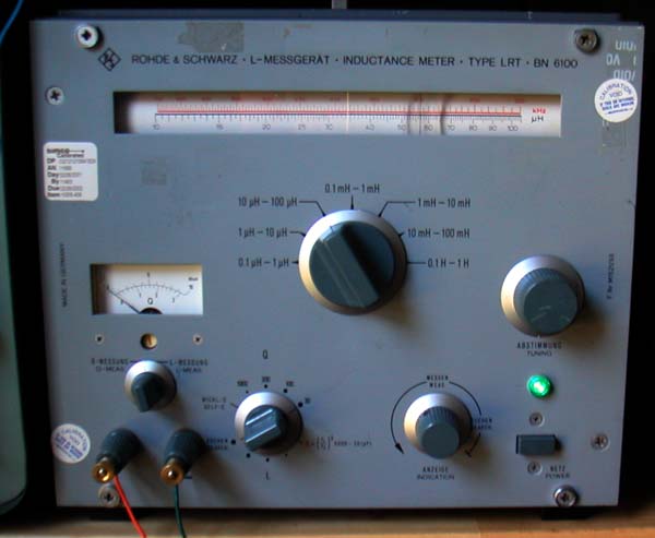 I measured these inductances with the venerable Rhode&Schwarz BN6100. It gives Q and inductance at a particular frequency that is shown on the top scale. A simple calculation shown on the table gives a normalized Q at 1MHz. This intrument has been extremelly useful in learning about RF inductors. It can only measure inductors that it can resonate, so they need to have a minimum Q to be measurable. For example, the Q of Audio transformers is often too low to be measurable here, and the inductance of audio transformers typically exceeds the 1H maximum inductance range.
The following table shows the variable capacitor values as a function of knob rotation. I set the zero of the knob to coincide with minimum capacitance.
| Dial | pF |
|---|---|
| 0 | 52 |
| 25 | 52 |
| 50 | 85 |
| 75 | 134 |
| 100 | 185 |
| 150 | 435 |
The dial only has markings up to 100 over a 180o rotation. The 150 value in the table indicates 270o. From this table, it is clear that I should rotate my dial position on the shaft by about 45o to make better use of he markings. No capacitance change happens for the first 45o.
While I was measuring inductance, I decided to measure the audio transformer. For this measurement, I applied a 10V square wave to the primary with a 1k resistor and measured the L/R time constant. The internal primary resistance is 474 Ohms and the time constant was 1.1ms this gives 1.474k*1.1ms=1.6H.
The audio primary to secondary step-up ratio was 1:4, so the secondary inductance is 16*1.6H=26H
Regenerative vs Homodyne reception
I had not played with a regenerative set in a long time. I was encouraged by the good results I was getting with my small loop, so I decided to examine regenerative action closely.


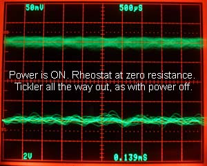
The out-most position of the tickler coil with the tickler knob pushed all the way in has some coupling, as we shall see.
The following sequence of scope photos shows what happens to the RF signal at the detector grid and audio at the second tube plate, as the ticker coil is moved from minimum coupling with the tickler knob pushed in, to maximum coupling, with the tickler knob all the way out.
I used the DM160 as the detector, and the CK5676 as described above.
The first photo sets up the measurement setings, and the second photo shows how much signal is at the detector grid when the power is off. This serves as a reference to assess the minimum regeneration that is possible with the knob all the way out.
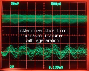
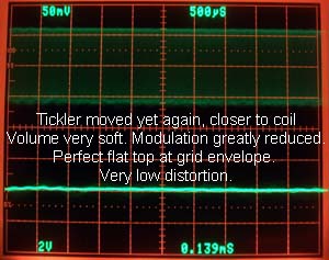
The variable capacitor was carefully pre-tuned to the station before this measurement series. Only the tickler moves for ever tighter coupling from one photo to the next.
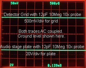

Turning on the power on the next photo made the audio signal appear as expected, and it also increased the signal at the detector grid. This proves that regeneration is present even in the most decoupled position of the tickler. The photo on the right shows maximum volume with some distortion, as the tickler was pulled in just below oscillation. Note that the RF signal at the grid roughly doubled, but the audio more than doubled. This shows that detection efficiency went up, along with an increase in RF gain. The increase of detection efficiency, more than the increase in gain, is the hallmark of regenerative detection.
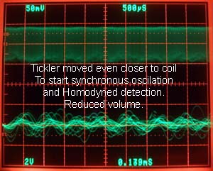
Homodyne detection
Now, the next photo shows a widening of the RF envelope that is caused by steady state oscillation in the detector. There is no beat note (whistle) because the oscillation is tuned to match the incomming frequency. The incomming signal also interacts with the detector non-linearity to keep the oscillation injection locked over a small range of tuning. The carrier portion of the envelope went up, and the audio output went down, along with a reduction in distortion. The photo on the right has more tickler coupling, and now a very obvious audio bandwidth widening could be heard. It sounds really sweet!
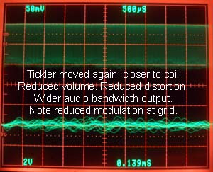
The next two photos show that increasing the tickler coil to maximum coupling does not cause a beat note, but simply continues the trend of increased carrier at reduced audio level. Note how flat the top of the envelope became, as the local oscillation increased.

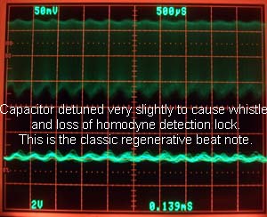
Lastly, detuning the capacitor slightly, produces the familiar regenerative beat note that occurs when too much regeneration is used, and the local oscillation is not locked to the incomming carrier frequency.
Homodyne reception is a form of synchronous reception. As such, it has several advantages:
- It can detect very small signals, if frequency lock can be established.
- It eliminates all adjacent channel crosstalk, because the adjacent channel is no longer envelope detected. The local oscillation moves the content of the two ajacent channels above 5kHz, assuming a station frequency spacing of 10kHz in the USA. (9kHz in Europe).
- Despite the excellent selectivity of Homodyne detection, the audio bandwidth is greatly improved. This is counter intuitive, but I am certain about hearing it.
- Distortion is greatly reduced. I think that this happens because one side of the envelope is completely flattened out, while the audio side amplitude is reduced and less involved in controlling positive feedback.
- As long as the oscillator stays locked, there is no beat note interference to radios nearby (I checked this). In fact, the synchronized carrier radiation is inconsequential, especially when compared with the LO leakage of many superhet sets.
- The very wimpy detector with a 22.5V supply, produces very little radiated power when it oscilates. I was using a loop for these experiments, and found it difficult to find the beat note on a good AM radio 6 feet away. I finally heard it, but it was weak. Typically I have more interference from computers in my home than this beat note.
These 1920's sets were made without resistors, as we came to understand them after 1930, and few or no large valued capacitors. They were made from metal, glass, vacuum and insulators. Yet they never cease to teach me all kinds of interesting lessons.
It would be great to hear any interesting experiences with these 1920's sets, or with regenerative or homodyne detection. I also look forward to any comments expanding, correcting or improving the material of this post.
Regards,
-Joe
To thank the Author because you find the post helpful or well done.
Excellent post

I read this post with great interest, since I have a 1925 Crosley 1121 Trirdyn awaiting restoration, and it also uses 201 tubes. It is considerably older than the radios I am used to working on, so I enjoy reading anythng related to receivers of this vintage. Thanks for posting that.
To thank the Author because you find the post helpful or well done.
Hand-traced schematics
Hello Michele,
Thanks for your very kind words. It is particularly gratifying to hear that my fun with this radio has made you think of having fun with your 1925 Crosley 1121 Trirdyn.
Your radio is a more sophisticated version of the 51, with one additional tube, but two additional stages. The additional tube is reflexed for use as RF preamp and audio preamp.
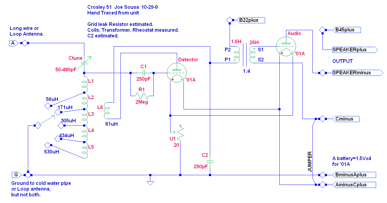
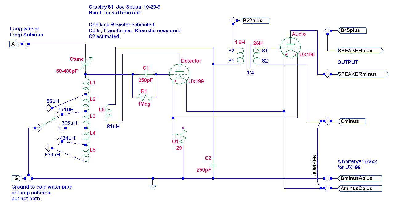
As simple as the Crosley 51 is, the published schematic data in Riders Volume1-16, is not consistent. The schematic diagram does not match the pictorial wiring diagram that was published on the same page. The differences revolve around the filament, rheostat and ground connections. So I decided to trace my set to see what I have.
The various tube types that can be used in this set differ in filament voltage. If using the original tube types, make sure both tubes take the same filament voltage because they are wired in parallel. (click to enlarge or save)
Crosley 51 with '01A (5V filament)
Crosley 51 with UX199 (3V filament)
Crosley 51 with modern battery tubes (3V A battery)
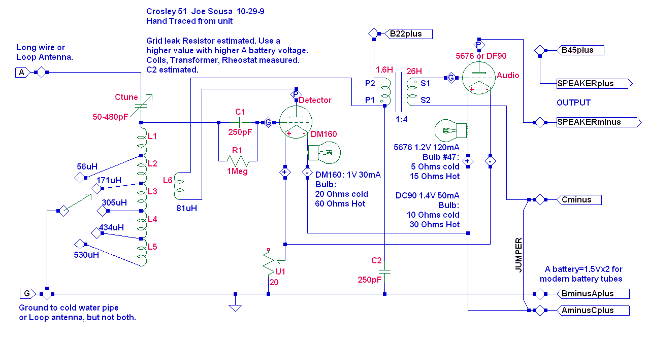
This last version of the schematic shows my home made tube adapters. I used light bulbs to drop the external 3V from the A battery to the lower voltage required by the more modern 1950's tubes. You can also use resistors with a value that is the same as the hot light bulb value, that is mentioned in the schematic. I used light bulbs only because I like to see their glow.
Loop Antenna update
In my first post, I mentioned that just about any loop antenna can be used with this set as an alternative to a wire antenna and ground connection. While this is true, some values of Loop antenna inductance work better than others.
The original loop, that I used for post 1, has 86uH of inductance. Since then, I tried a larger diameter loop that has 150uH of inductance. While I was still able to tune most, if not the entire AM band, the regenerative action was reduced at the high end of the AM band because the internal antenna coil L1 is only 56uH, while the external loop is 150uH. This means that a relatively small portion of the input circuit inductance is involved in capturing the feedback from the regenerative feedback coil L6=81uH.
Comments invited.
Regards,
-Joe
To thank the Author because you find the post helpful or well done.
3A5 sub with switched filament
One problem with many Crosley 51 radios, like my set, is the shunt that comes prewired in place of the Cminus battery. This means that the Grid of the audio tube will be somewhat conductive with zero grid bias and will load the high impedance output of the interstage audio transformer.
In the previous posts I described methods to introduce 1.5V of Cminus bias in series with the filaments of 1-1.5V substitube tubes. Perhaps the most convenient method to introduce this 1.5V bias is with a substitute tube, such as the 3A5 dual triode, that has a 3V tapped filament.
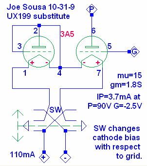 Only one of the two triodes is used in this scheme. The unused triode plate and grid are tied to the center tap.
The filament of the second triode is still used to provide the proper drive from a 3V "A" battery, and to provided switchable 1.5V of cathode bias.
In one position of the switch, the inactive filament is connected to the minus pin, thus raising the active filament by 1.5V. This is the position that is useful in the audio amplifier application.
The other position places the inactive filament on the positive side of the "A" battery connection, thus lowering the active filament cathode to the most negative bias level. This is generally preferred when the tube is used as a detector, especially if the external grid leak resistor is tied to the minus terninal of the "A" Battery.
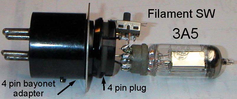
I built the filament switch, which does nothing more than swap the filament terminals, onto a 4 pin plug. This plug is fine to use in UX199 sockets, but does not work in bayonet four pin sockets that are usually used with '01A tubes. The photo shows the adapter I built using a discarded tube base and a new tube socket.
A few substitute tube disclaimers
While none of these substitute tubes are exact replacements for the 3V 199, or the 5V 01A, they can still work quite well. All of these tubes have higher gain than the originals and, generally, a lower filament voltage.
The higher gain that is most likely to be troublesome is the voltage gain mu, which is around 15 for most of the substitutes, while it was about half that for nearly all 1920's small signal triodes. The higher mu means that the Cminus bias voltages must be reduced. Doubling the mu requires half the Cminus voltage.
Another effect of a high mu is that the grid conductance will be less dependent on plate voltage. This means that a tube with a mu of 8 may not need any C- bias to keep grid impedance high. While a tube with a higher mu, may need some C- bias to keep the grid conductance low.
The transconductance of the substitute tubes runs between 1 and 2mS. This is generally OK, but sometimes, the added transconductance gain can cause oscillations. The transconductance of the 01A is 0.8mS and for the 199 is 0.4mS.
The higher filamentary voltage also has a significance beyond the choice of "A" filamentary battery. The most glaring example of this difference is the '01A with it's 5V filament.
For example, when the 01A is used as a detector, with the plate at 22,5V, only the section of the filament that is within 22.5/8=2.8V of the minus filament terminal is not cutoff. Nearly the entire upper half of the filament is cut-off. The voltage gain factor mu for the 01A is 8, and a good rule-of-thumb to calculate grid cutoff is to divide the plate voltage by mu.
Nearly all tubes work well as audio amps, once some Cminus bias has been applied. The suitability as detectors varies more from tube to tube. I had the best results with the DM160/6977 as detector
Regards,
-Joe
To thank the Author because you find the post helpful or well done.