NiMH Battery packs for High Voltage
NiMH Battery packs for High Voltage

Forum friends, I will share with you various methods of building high voltage battery packs for Battery radios. These could be 1920's sets, up to 1960's portables.
I have been making high voltage batteries from rechargeable NiMH 9V batteries.
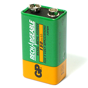
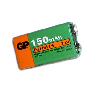
NiMH "9V" rechargeable batteries are usually made from 6 cells of 1.25V each. This only adds up to 7.5V for NiMH. The "9V" value is a standard value that came from 1.5V carbon zinc cells.
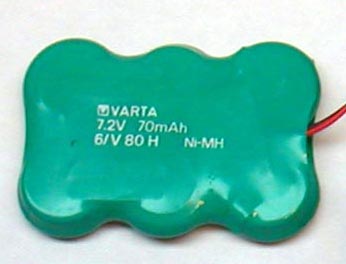
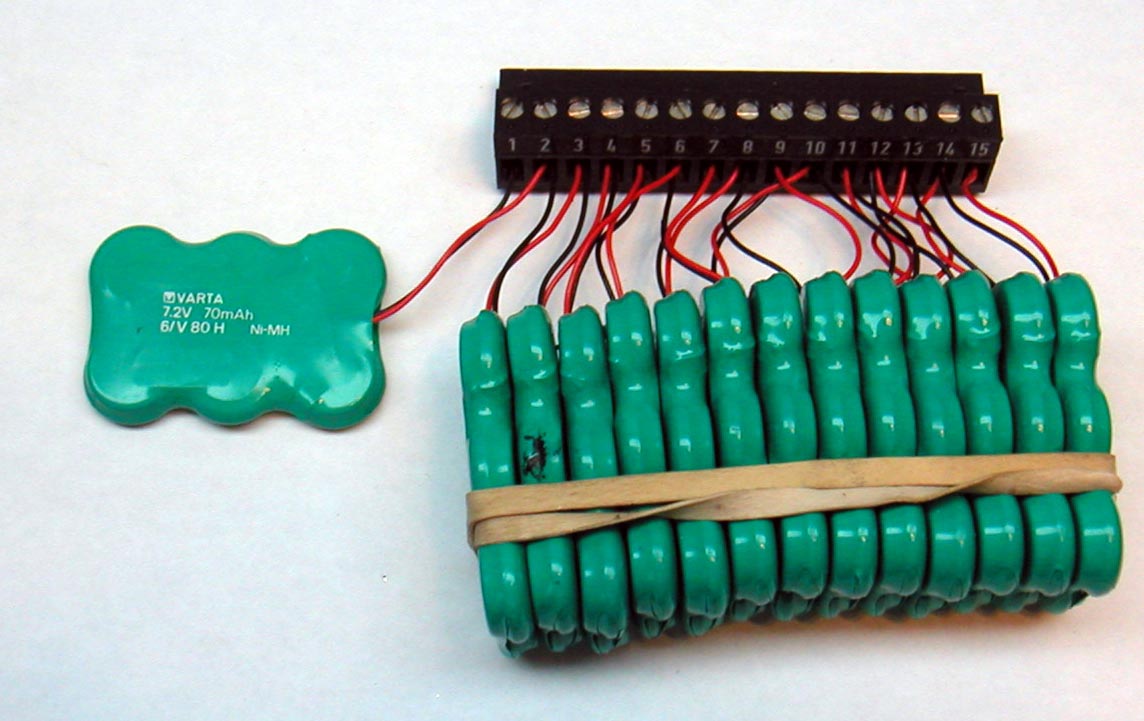
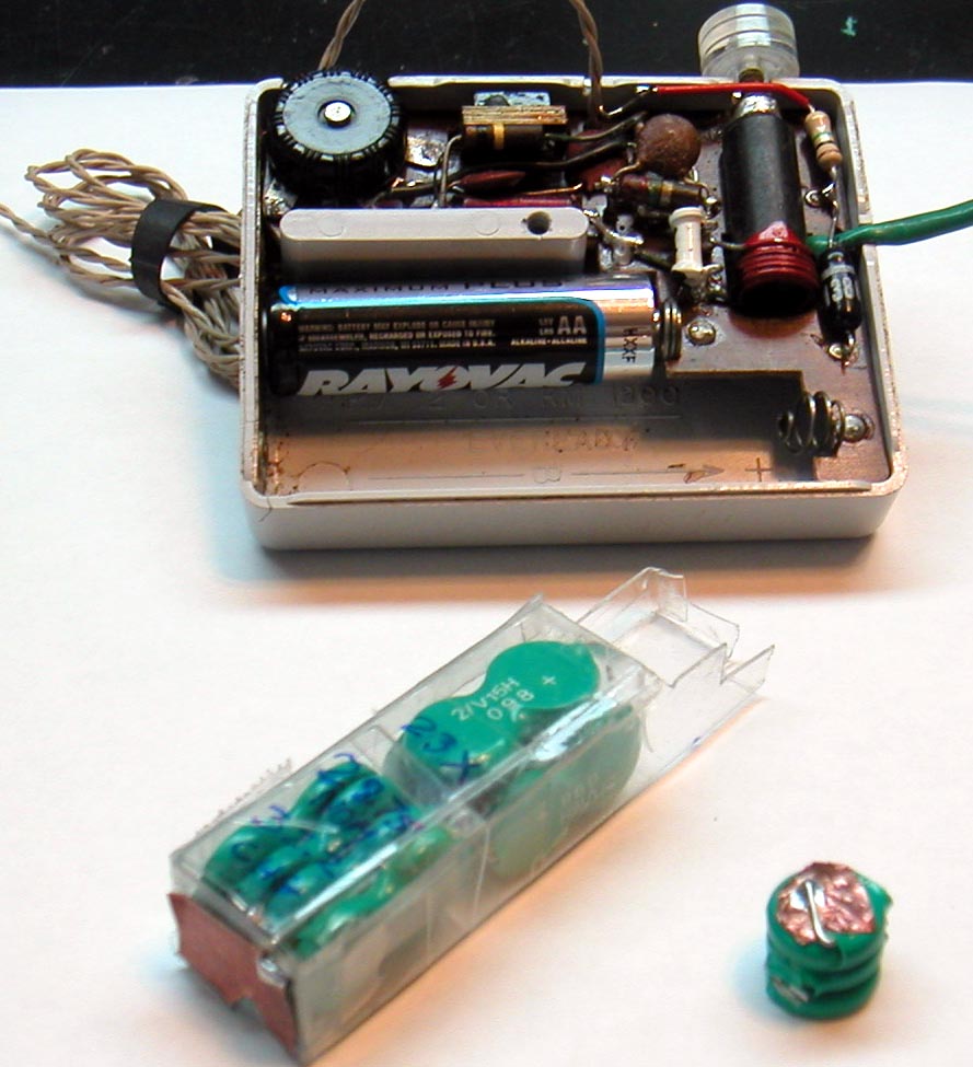
I have built packs from standard sized 9V batteries, and from smaller sized 70mAh cels from Varta, as shown in the photos below. I got these smaller cells from www.goldmine-elec.com, but they are sold out on this size. This battery was originally made for the Real-Time-Clock in a laptop computer.
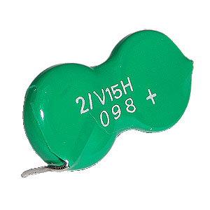
They still have the standard 9V size for $1.79USD, and these very small 2.5V two cell packs for $1USD.
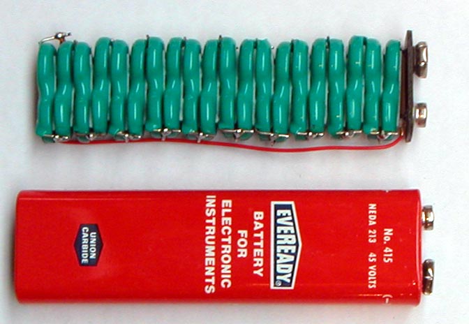
I have been able to make a 50V pack with 20 of these, that has the height of two standard 9V cells and could be used to substitute for an Eveready type 415.
 Each 2-cell pack comes with self-adhesive foam.
Other sources for NiMH batteries that could be used to build HV packs include:
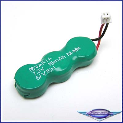
http://www.pcsurplusonline.com/index.cfm/product/181/72v-15mah-ni-mh-cmos-battery-for-dell-inspiron-500m-600m-latitude-d600.cfm
With this cell selling for $3.99USD
and
http://www.sciplus.com/category.cfm/subsection/13/start/23/maxrows/11/srch.fp/1
with this 3.6V 280mAh 3xCell NiMH battery for $1USD each

I have built some of my packs as hard-wired series stacks, and also as switchable Series/Parallel packs.
The series stacks are used and charged at nearly the same nominal voltage. The operating voltage under load for the NiMH cells is 1.25V, and the charging voltage is 1.4V. This 1.4V value is safe for unlimited time charging. These values are for one cell, so you need to multiply by the number of series cells for the final operating and charging voltages. A 90V pack is made from 72 cells, or 12 "9V" NiMH batteries. The charging voltage for this pack is 1.4x72=100.8V.
The series/parallel switchable packs offer the possibility of operating in series, at a high voltage, while being charged in parallel, at the original individual pack voltage. The parallel charge method also offers the benefit of equalizing the individual pack voltages to the same value, thus prolonging pack life. When one of these packs is not used for a long time, it is also beneficial to keep the pack switched to it's parallel position. The low precision voltage needed for parallel pack charging is also more commonly available in a home lab.
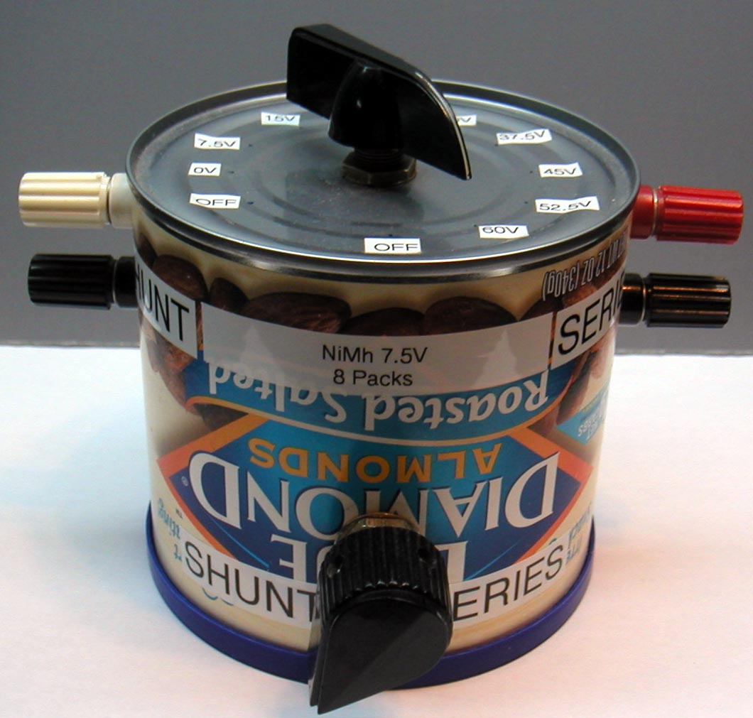
The following is an example of a general purpose series/parallel 60V/7.5V pack that I use in my lab. The lower knob switches the pack between series and parallel configurations, and the selector at the top selects the tap voltage on the pack in series mode that appears at the banana jacks on the right. The set of banana jacks at the left is for the shunt 7.5V connection.

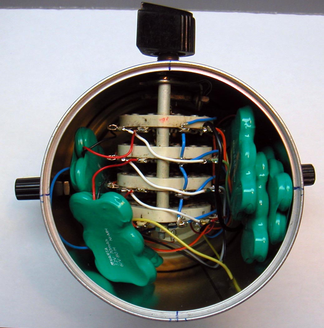
The following shows the wiring diagram for one wafer of the series/shunt switch. I used some rugged military surplus Russian switches from ebay seller KWTUBES.
 Righ-click and save for higher resolution.
A hard-wired pack with 14 6xNiMH batteris for 1.25x6x14=105 nominal operation and 1.4x6x14=117.6V charging voltage. The black bar offers connection points to any tap in 7.25V increments.
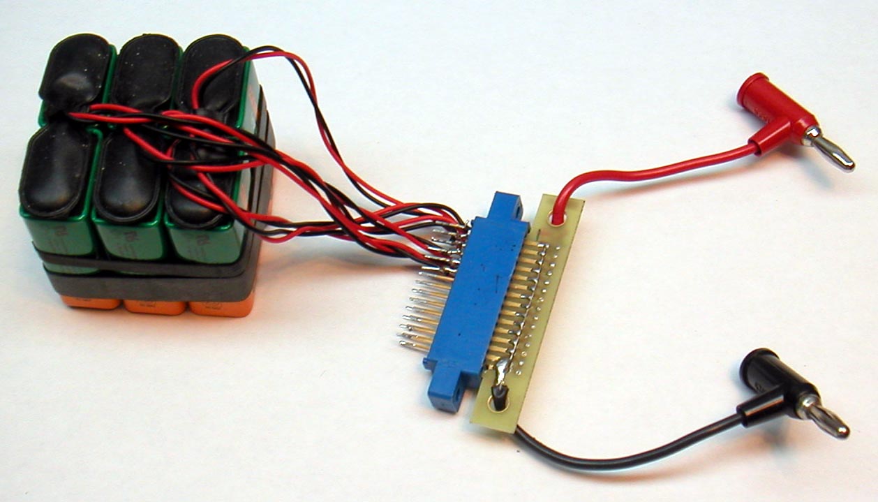
Another general purpose 45V pack made from six "9V" NiMH cells. The series/shunt switching is done by the plug-socket arrangement. The card-plug shown is for the parallel connection. A different card plug wires the cells in series for 45V service. The batteries are held together with rubber bands made from bycicle inner-tubes. The neoprene rubber lasts much longer than natural latex.
The following pack follows the same construction method and was built to supply 90V to my Grundig Concert-Boy 57. This pack was shaped to fit in the existing battery space, which was quite ample. Both series and parallel card-plugs are shown here. The series plug was fitted with snap connectors to mate with the original battery cap seen on the left.
 The empty battery slot on the right was meant for an external 1.5V D cell, which works in parallel with the internal 1.25V NiCd cell. I replaced the internal cell with a 1.25V NiMh C-cell with a 3600mAh capacity. This cell is always charged by the radio. The 90V pack may be charged by the radio, or externally, in parallel configuration.
This hard-wired series pack was a challenge to fit in the original Emerson 838 radio. I also made a custom 3xAAA cell holder and battery cover. The packs are all 6cell types, of 70mAh capacity. All packs, except for one were folded to fit.
I also had to make a battery cover from PCB stock.

This pack shows a somewhat baroque series/parallel switching method for a 90V pack in a Zenith Trans-oceanic G500. The series/parallel switch is made from individual DPDT slide switches soldered together. A stiff wire runs through the plastic sliders. It works, but is a bit stiff. I used standard 6xD battery holder for the filament voltage. Both packs connect to the original 4 pin socket with an improvised 4-pin plug. The design of the battery wiring in this radio is a bit peculiar. It is possible to blow open one of the filaments if the batteries are not all connected together. When changing batteries, make sure the power is off, and the 4pin plug is disconnected.
![]()
![]()
A series/parallel 67.5V pack for the RCA BP-10. Note the Neoprene bicycle inner tube rubber band, and the heavy plastic bag to avoid shorts. The original battery snaps plug into the series card-plug.
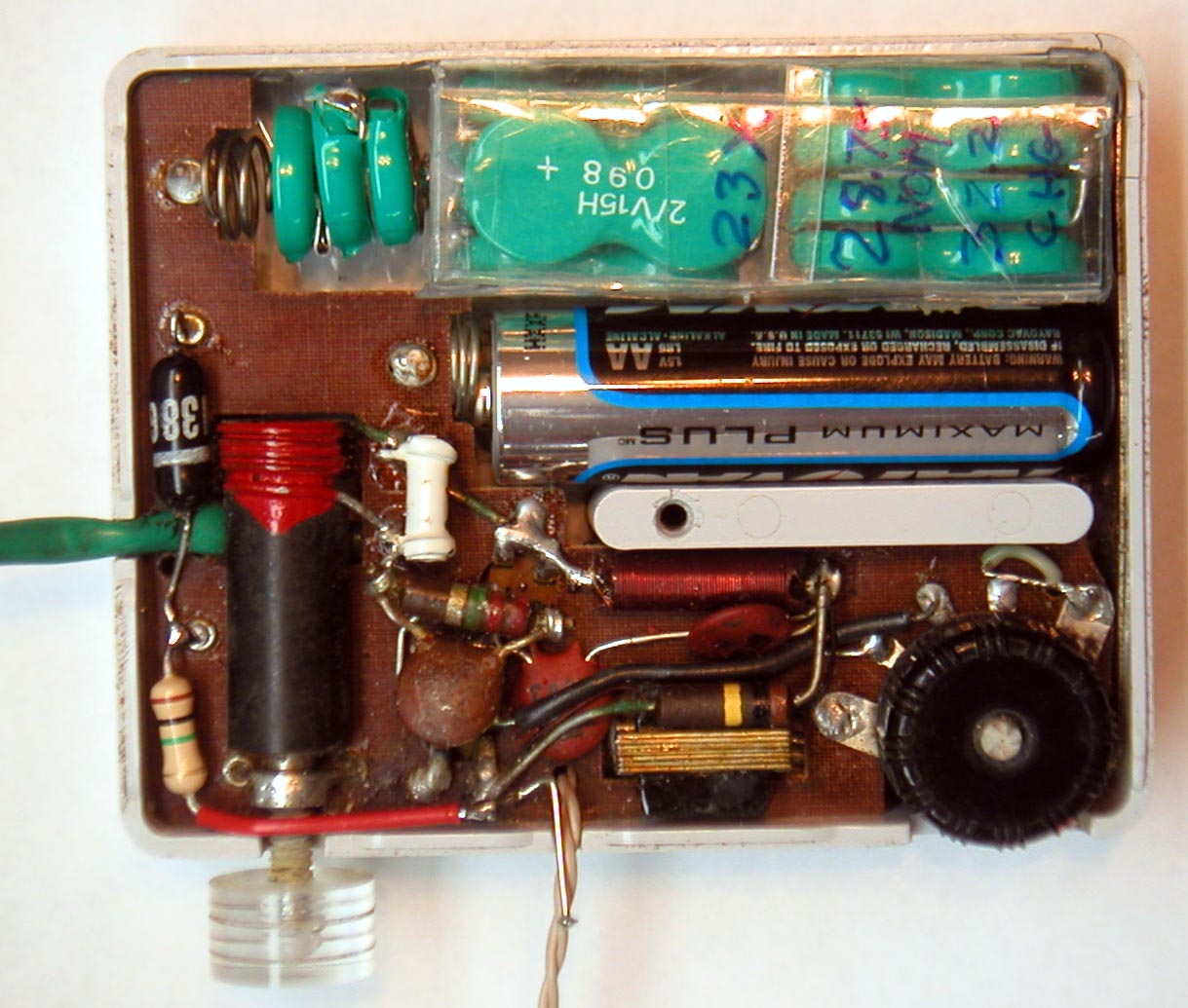
The smallest pack I have made so far was for my recently acquired Hastings FMJr. I made the pack from 11.5 two-cell Varta packs mentioned above. The first 10 batteries are packed tightly inside stiff plastic found in electronics packaging. The additional 3 cell stack was made from a folded 2cell battery, and a single cell. The last battery had to be a single cell because I could not fit the full 2cell pack. The shaping of the plastic pack was quite time consuming, but worthwhile. The operating voltage is 23*1.25V=28.75V and the charging voltage is 23*1.4V=32.2V.
The follwoing packs were built into wooden cases to match the styling of this 1920's Silvertone-Trav-ler portable radio. The packs replace the series connected A size 1.5V drycells and the 67.5V B+ battery. The low voltage pack now provides a regulated 3V for the filaments, and unregulated 60V for B+. The 4.5V C- voltage is currently provided by a series connection of 4 button cells, which are barelly visible just above the second tube from the left. The 60V pack is a series/parallel pack wired like the battery can above. Both wooden boxes include voltage regulators f, such that unregulated voltage from wall transformers can be used directly for charging. Note the heat sinking to prevent overheating during charging. The original arrangement for the A cells was with the 3 cells lying on the shelf, with the cell connection posts facing out.
.JPG)
.JPG)
.JPG)
The last pack was made to power a 1920's FADA 160 American TRF three-dialer. This was my first 1920's battery radio. This radio gave me quite an unexpected learning experience. It was designed before semiconducting carbon composition resistors were invented. Imagine a radio built from various forms of wire, metal plates, insulators, glass and vacuum! (This is, of course, "very old hat" for most RM members)
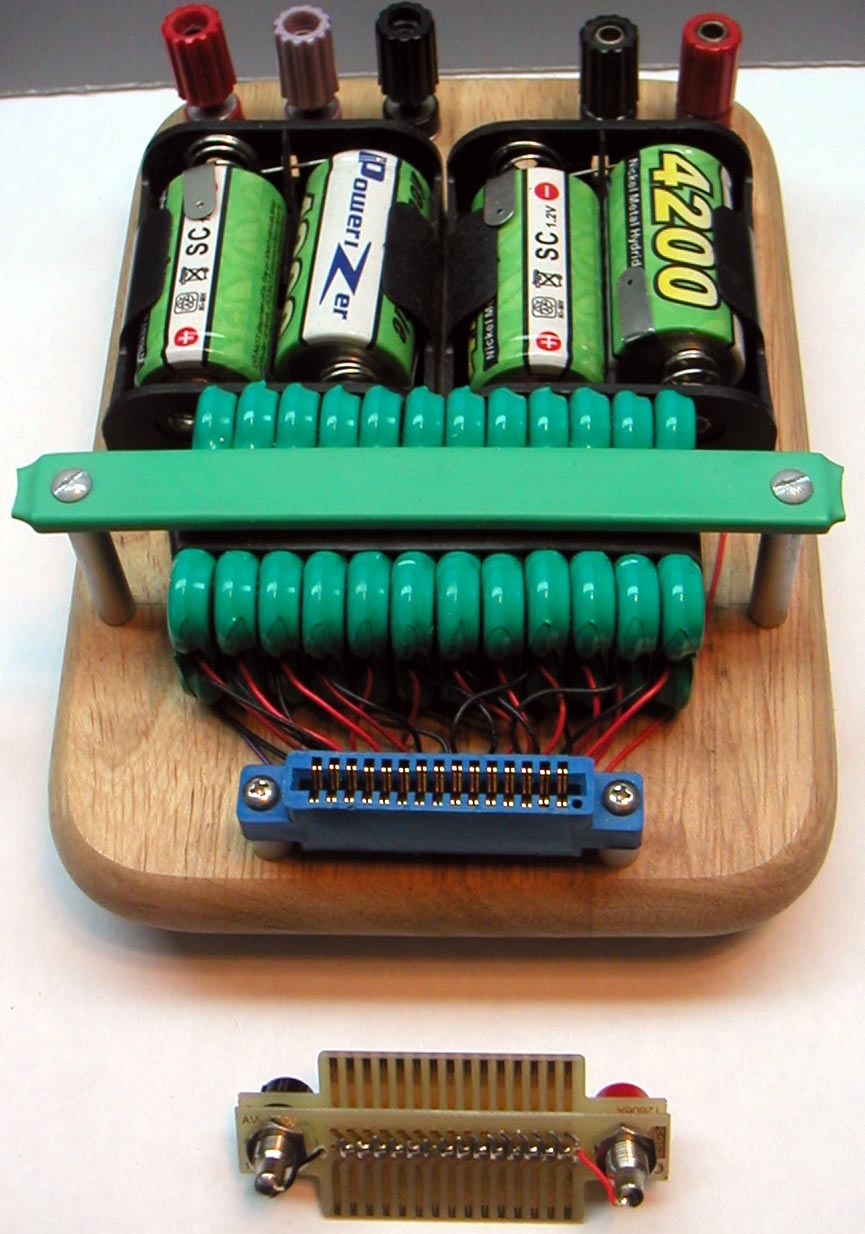
This pack has 4 series wired NiMH 4200mAh sub-C cells to supply 5V to the filaments directly. The 12 batteries in the 90V pack are wired in the series/parallel switchable configuration, with a tap taken at 22.5V for the detector voltage. I mounted the series and parallel card plugs together. If the plug is inserted as shown at the left, the pack is wired in series for 90V&22.5V service. Parallel wiring for recharging the 7.5V batteries with 8.4V is obtained when the plug is flipped 180o, such that the charging banana jacks face outward. The nice looking piece of wood was bought as a small ready-made bread-board.

A cautionary note on NiMH and NiCd batteries: These batteries have extraordinarily low internal impedance. When shorted, they can produce several amps of current and cause a fire. Care should be taken with wiring schemes to prevent shorting the batteries with an accidental incorrect plugging in of the cells. Insulation should also be done robustly.
After posting all these photos of packs built from the 7.5V 80mAh packs from www.goldmine-elec.com, I think I realized why their stock ran out: I probably bought most of them!
Comments invited. Regards,
-Joe
To thank the Author because you find the post helpful or well done.
? Charge device

Hi Joe,
now, we are waiting for the suggestion of a sophisticated charge and supervise circuit.
I have seen a chip called LTC6802-1, hell knows from whom it is? :-)
Georg
To thank the Author because you find the post helpful or well done.
Linear Technology Corporation (LTC)

More information you will find here ...
cds.linear.com/docs/Datasheet/68021f.pdf
To thank the Author because you find the post helpful or well done.
Constant 1.4V/Cell Charging
Hi Georg,
The LTC6802-1 was designed recently by one of my LTC colleagues in California. I am in Massachusetts designing ADC's, but one wonders if I don't suffer from power supply design envy, with all these battery packs I have built...
The LTC6802 is clearly overkill for this application. It was meant to maintain NiMH batteries in electric vehicles. But someone could have fun playing with this part, especially if it is to be used with a high drain radio that is frequently used.
My answer to sophisticated charge ballancing of the LTC6802 is to use parallel charge as much as possible to force packs into charge equilibrium.
My charging method on all these packs is to simply apply 1.4V times the number of cells in series. This charging method is substantially slower than the more sophisticated methods, but it is very safe for the batteries, and trouble free, in that it is not necessary to time the charging.
The 1.4V charging voltage also has the simplicity that all NiMH cells, regardless of size, will eventually taper off to a charging current level below trickle charge. Typically, I charge my packs with fixed voltage overnight, or over a day or two, or a week. I disconnect them, when I finally remember that the charging is complete.
The charging current profile from a fixed 1.4V per cell is somewhat like that the response of an RC circuit: There is a initial high current, then it tapers off more or less exponentially to a low steady state value that does not exceed the recommended trickle charge current. Trickle charge is the current level recommended by the battery manufacturer for continuous charging.
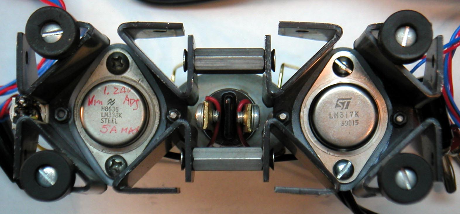
The various chargers I have built were made from simple linear adjustable regulators, that were set for the intended number of cells. These regulators also provide free current limiting. You can see examples of the regulators built into the wooden boxes of the Silvertone-Trav-ler. By the way, I bought the wooden boxes ready-made at a craft shop.
My favorite adjustable regulator these days is the LT3080 single resistor adjustable and parallelable linear regulator. You can see it in the Silvertone-Trav-Ler battery boxes. The data sheet is available at
http://cds.linear.com/docs/Datasheet/3080fa.pdf
The RM archive also has some basic application and pinout information about the LT3080.
This regulator uses an innovative elegant architecture, and was conceived and designed recently by our reveered LTC Vice President and CTO (Chief Technical Officer), Robert Dobkin (Dobbie among LTC enginneers).
I also built a more permanent charger that puts out 5.6V for 4-cell packs and 8.4V for 6cell packs. I used linear regulators for both, but added ampmeters in series with the regulator inputs. The regulators were powered by a surplus 12V 2A black power supply brick, similar in shape to the kind used for laptop computers.
I also added a 12V 1A bulb in series with the 5.6 regulator to lower the voltage applied to the regulator when under heavy load. This also gives a visual indication of charging condition.
I also added a 6.3V 300mA bulb in series with the wall transformer that drives the charging regulator for the HV packs in the Silvertone-Trav-ler. I enjoy seeing the brief flash of light when I switch the black knob on the HV pack from series connection for the radio load, to parallel connection for charging. I have no other visual indicator of charge in this setup. As the batteries charge, the bulb dims completely. I usually leave this radio permanently connected in parallel charge mode when I am not listening to it.
One additional benefit of the series/parallel charging scheme for the Silvertone-Trav-Ler is that, even with the chargers permanently plugged in, this loop antenna radio is not grounded via the charger wire when the radio is in operation with the batteries in series. AM radios with loop or ferrite antennas often pick up a lot of interference when they are grounded.
If you need to see more detail on all the photos I posted above, simply click for a higher resolution version.
Regards,
-Joe
To thank the Author because you find the post helpful or well done.
NiMH chargers
These Photos and Schematics show the charging circuits I described in the previous post.
First, the schematic for the the Silvertone-Trav-Ler portable 1920's radio shown above. It includes the two wall transformers and series/parallel comutator for the 60V Bplus pack. The charger for the 3V filament voltage includes a power line filter because this charger may be connected while the set is running. The Filter prevents interference. The 3.75V/4200mAh NiMH filament battery is not connected directly to the 3V filaments, but through a simple LDO regulator I designed, using commonly available parts. I made this regulator to guaranty that I would not destroy the tubes with over-voltage. The radio includes a voltage droping resistor for the filaments, but I did not want to take a chance with having this rehostat set incorrectly.
Click for full resolution
The following schematic and photos show the circuit of the general purpose charger I use to charge all the packs described in the first post.


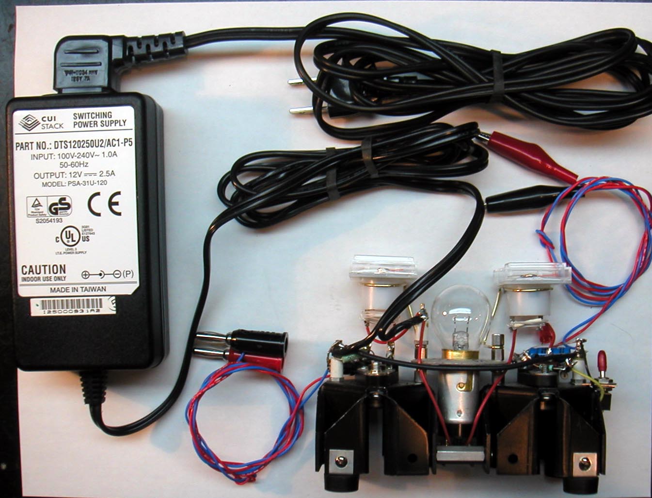


The following is an additional charging head I made for standard sized "9v" Batteries. I use some of these batteries in pocket DVMs. The 9V snaps you see mounted on the recycled PCB were salvaged from dead 9V batteries.

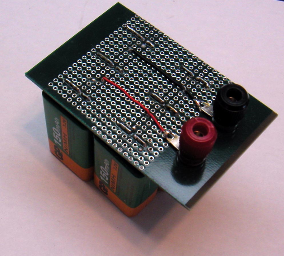

The banana jacks at the top take charge from the 8.4V output of the general purpose charger.
Regards,
-Joe
To thank the Author because you find the post helpful or well done.
NiMH (V with 7 cells
Radiophile friends,
www.goldmine-elec.com now has NiMH 9V batteries made with 7 cells (G16511) .The price is $1.50USD each. The 9V battery format usually only has 6 cell, but this particular type has one extra cell to make up the lower voltage that NiMH cells (1.25V) supply, when compared to alkaline or Carbon-Zinc cells (1.5V).
These new 7cell NiMH batteries supply 7x1.25V=8.75V, and could be charged up to 1.4V*7=9.8V.
You need to be careful in not connecting 7cell batteries in parallel with 6cell batteries, when you parallel charge the cells. This erroneous connection would produce very high currents that could overheat the connecting wires.
The 7cell batteries look very similar to the 6cell batteries. Both availabe at Goldmine.
I bought a 10 piece lot of the 7cell batteries with good results. The higher voltage of the 7cell batteries is particularly useful in portable meters.
Regards,
-Joe
To thank the Author because you find the post helpful or well done.
Safety for 'Ni-Mh battery packs for High voltage'
Count of Thanks: 53
Hi Joe,
I hope you will put a fuse or two in your battery assemblies to protect against accidental fires.
Perhaps you can try positive co-efficient resistors, like those used in loud-speaker protection.
Those will need some careful trials though.
Good luck,
Clive.
To thank the Author because you find the post helpful or well done.
Battery energy
Hi Clive:
I always add fuses to NiMH packs made with AA size or larger. The 9V sizes don't store enough energy to cause a fire with a short with a 20 AWG wire. However, when several 9V cells are wired in parallel for charging as recommended above, a fuse in series with the shunt charging combination is necessary. I used a microfuse in the PCB shunt/series plugs. Some experimentation could be done to see if there is series combination of 9V NiMH cells that could over-heat a wire short.
My favorite positive tempco resistors, that also serve as fuses, are light bulbs. But these can't be applied with the same reasoning as fuses because the current levels that take advantage of the positive tempco are much lower than the current that would burn out the bulb. Nevertheless, when applied correctly, lightbulbs can be effective protectors. You see at least one light bulb used as ballast in the circuits above.
I have used light bulbs in series with low voltage packs or power supplies, with a bulb voltage and current rating that simply results in the lightbulb lighting up normally when there is a short. This works when the expected load current is much less than the bulb current rating.
Best regards,
-Joe
To thank the Author because you find the post helpful or well done.
NiMH direct 90V, NiMH 6, 7.5 or 9V and 'Coin Cell'options
I was considering packs made from AA NiMH. But I was worried about one or two cells getting destroyed by reverse charging as the HT pack discharged. Then there is also the difficulty of charging.
Yet I didn't want an inverter. Though Vibrator packs for HT from LT date from the 1930s and I beleive all the Russian Military valve sets of 1950s and later used vibrator for HT. However I designed several LT1073 based boost and Cuk inverters to use 6 x C cells (it all fits in a B126 box)

Screen can of coffee tin behind 6 x C NiMH pack.
A reed switch connectes inverter to battery and is activated by 5 layers of wire wound on it. The wire is in series with LT battery and causes about 80mV drop. Switch operates about 105mA, drops out at 60mA.
Why the old LT1073?
It can handle 50V on its switch transistor, so a low current 90V supply (78V is enough as it doesn't droop) can be achieved with a doubler version of the Boost inverter.
Also for higher volts a 1100pF gate cheap PC PSU 900V FET can be driven. Then the 19KHz is an advantage. However I'm looking at a step up isolated dual transformer Cuk using MC34063 at about 90kHz (harmonics must avoid 198KHz and 252kHz +/- 10KHz in case filtering isn't good enough, R4 LW and RTE1 LW)
I also found a source of CR2032 Lithium coin cells about 7 cents Euro each. So I put 6 stacks of 25 coils in a B126 box coupled with 6 x 1N4148. This works out about 11€ inc postage. Not cheap for a disposable battery? But that's for at least 200mAH x 6= 1.2AH. Also very low droop to endpoint compared to NiMH, Alkaline or Zinc Carbon. With a 7mA HT, that is over 170hrs. Would the original B126 been much more than 15hrs?
Each "stack" of coins is 26 cells, so 156 x CR2032!
However I am considering a NiMH pack without inverter and PIC to monitor each cell and disconnect pack before any cell reverse charges. Options are AAA and AA cells depending on pack size. AA cells do give best value in NiMH.
If something is used a lot and heavy current draw then the NiMH only stack is best capacity and value.
If filtering and screening is good and you don't mind an inverter, then maybe 7.5V of C or D cells to run series LT and HT inverter may be an option.
A about 0.07 € a cell inc postage from Hong Kong to Ireland, for intermittant use (10 year shelf life?) the CR2032 are worth considering. But you need multiple parallel stacks as the current per cell should not really exceed 2mA and 1mA is ideal. So 6 stacks parallelled via diodes for 6.5mA nominal HT is OK in a B126 box.
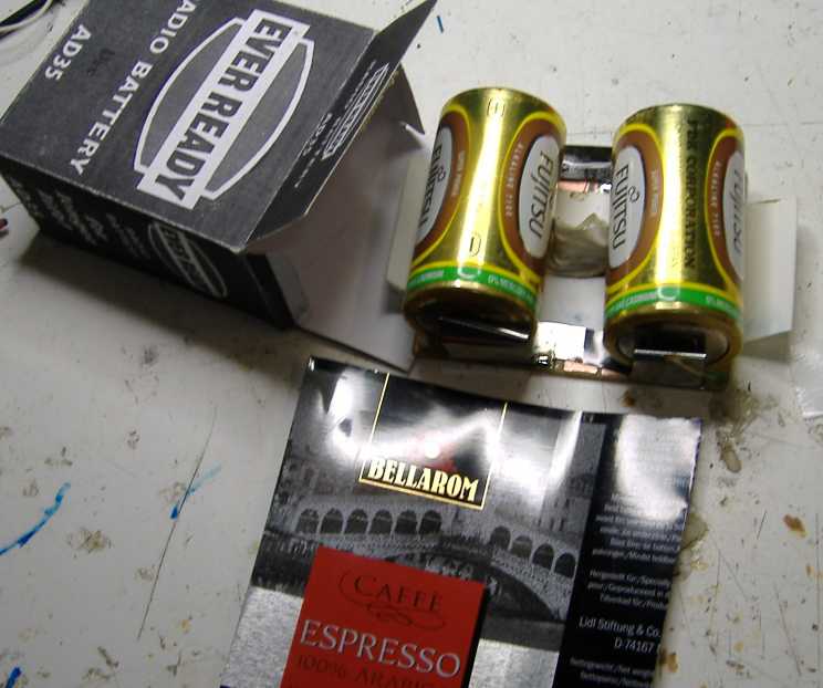
LT AD35 pack 2 x D Cells in parallel. Coffee tin holder on plain PCB
The sockets are made from cut up coffee tin solderd to blank PCB scored and isolation lands lifed with knife.

Cut up margarine tub, coffee can tin plate for + common of all six stacks, 6 x coffee tin strips and 6 x 1N4148 diodes on the -V end (to right of photo) and final top B126 socket made of curled and cut coffee tin on plain PCB. Paxolin, so the three holes just poked with screw driver.
Glue, solder, scissors, thin card, coffee tin, margarine tub, plain single sided paxolin PCB.
B126 and AD35 printed on paper and glued to 200gm card.
Conclusion
Stacked NiMH alone, NiMH + inverter or cheap CR2032 are all better than using Zinc Carbon 10 x PP3 batteries in lifetime and value. For Disposable solution the CR2032 beat Alkaline 9V cells in shelf life and operation time and may be cheaper too.
The "best" solution may be influenced by your construction skills and usage pattern of the Radio.
Attachments:
- 6 xC NiMH and Inverter (108 KB)
- LT pack of 2 x Alkaline D Cells (42 KB)
- 6 x coin stacks (62 KB)
To thank the Author because you find the post helpful or well done.
2.5 volt cell in series to make 50 volt pack.
Count of Thanks: 48
To thank the Author because you find the post helpful or well done.
Problems with High voltage NiMH stacks
There are two serious issues.
1) As the voltage is higher (more cells) it gets harder to ensure that on discharge one cell isn't getting destroyed by reverse charging. Lithium packs solve this by having an internal CPU and measuring every cell.
2) On charge you need to charge well below 1/10th C and outside the radio set as terminal voltage with say 75 cells assuming nominal 1.2V will rise from from 90V (75V to 83V at fully discharged) to over 115V!
It's best to charge the battery packs or cells individually. I've seen high voltage packs with built in relays to have cells or packs in series when not on charge and on charge the relays are energised and the cells or packs charged individually. This allows turbo charging, then 1/10th C then a tiny maintenance charge. Very high capacity packs and also Eneloop types (usually medium capacity) NiMH can't be left even on 1/10th trickle charge without dramatic shortening of life.
Joe Sousa shows the arrangement to switch from series to parallel to charge on an earlier post.
Better to use Alkaline or Lithium Coin cells for HT
On old valve (tube) sets the HT current is typically 5mA to 15mA range and thus Alkaline or CR2032 coin cells (for small packs) are economical and can have 5 to 10 year shelf life. The high capacity NiMH can self discharge in a few weeks and only the Eneloop type will keep charge for over 6 months.
Small packs can use CR2032 lithium coin cells (15c each from Hong Kong inc postage). Note that as the end point is about 2.8V per cell you don't need 15 cells for 45V nominal pack (30 layer Zinc are used) but about 11 cells (30 divided by 2.8). Larger packs for sets with more HT current should use 6 x 1N4148 diodes to parallel 6 stacks) For safety a micro fuse must be used as a shorted 90V pack of Lithium coin cells will overheat and catch fire.
Best old Radio application for NiMH
However the NiMH are ideal for the filaments as it stresses them less than Zinc Dry cells and they take 24mA to 275mA (series or parallel) at nominal 1.5V to 9V. In fact 1.5 LT is ideally 1.35V (NiMH nearly fully charged) to 1.1V (NiMH end point) per filament. so:
| Nom. | Tube | Zinc Dry Cell | NiMH typical | ||||
|---|---|---|---|---|---|---|---|
| Volts | Ideal | Qty[6] | End | New[1] | Qty | End | Full[2] |
| 1.5 | 1.35 | 1 | 1 | 1.6 | 1 | 1.1 | 1.4 |
| 3.0 | 2.70 | 2 | 2 | 3.2 | 2 | 2.2 | 2.8 |
| 4.5 | 4.05 | 3 | 3 | 4.8 | 3 | 3.3 | 4.2 |
| 6.0 | 5.40 | 4 | 4 | 6.4 | 4 | 4.4 | 5.6 |
| 7.5 | 6.75[5] | 5 | 5 | 8.0 | 5 | 5.5 | 7.0 |
| 9.0 | 8.10[5] | 6 | 6 | 9.6 | 6 | 6.6 | 8.4 |
This shows that while NiMH are poor choice for HT due to discharge limit issues and charging difficulty they are excellent for LT. No-one is making battery tubes anymore. Thus mains opertation should be set just below the ideal (more than double life compared to 1.4V per filament).
Putting fresh Zinc Cells on every demonstration can reduce tube life to less than 1/2.
Notes:
- IEC takes 0.9V as end point of Zinc Carbon, Zinc Chloride and Alkaline, but "balanced" battery packs assume 1V per Zinc cell as the tube performance is too poor. Most L.O. stop at 1.0V or just a bit less filament. Initial no load voltage is as high as 1.7 on Zinc (1.6 on Alkaline). Falls quickly to 1.6V, the flattest part of curve is 1.5V to 1.3V when it falls rapidly again to 1V. At 0,9V it "falls of the cliff" (Zinc). The Alkaline are flatter discharge curve, but tend to "pop up" to about 1.25V to 1.3V on no load when flat (1V and less on load).
- NiMH terminal voltage on load without charge is initially about 1.4V. It rises to over 1.5V when fully charged on charge with no load. It quickly falls to about 1.35V. NiCd are about 0.1V lower per cell for most of usage. Exact voltage depends on cell size, discharge current and duration..
- Capacity. The x5 capacity of Alkaline vs Zinc Carbon is a myth. This is only at high current draw when life of Alkaline is shorter life than NiMH. At low currents (series filaments with D cells or HT with AAA cells) the Zinc Chloride is about 1.3x more life and Alkaline x2 life.)
- NiMH is about 80% capacity of Alkaline at medium current draw but up to x4 life at very high currents. For Clocks, Calculators, Electrets, HT current, Grid Bias etc an Alkaline may last x10 to x100 longer than NiMH.
- Series filaments are complicated by the current from Anode (Plate) and Screen/g2 which can be 10% or more on output tubes.
- In general the quantity of Zinc Cells equals the quantity of series filaments.
- The European Continental sets often used a single NiCd LT and also "regulator" on mains operation. With a modern NiMH the voltage may be slightly higher, just over 1.5V on fully charged, so don't leave charging when off. US & UK sets often used series filaments and a dropper (or in USA Barretter and dropper) from the HT voltage.
To thank the Author because you find the post helpful or well done.
Laptop/Notebook Lithium packs
Lithium packs on Laptop, Notebook etc
Just to clarify an earlier ambiguous comment, the Lithium packs on Laptop, Notebook etc are typically only using per cell monitoring to end series charging or usage. The on board CPU communicates what is happening via a serial bus connection. The number of cycles is also counted which is why cell replacement often isn't viable. Larger capacities use a mix of more cells in series and/or pairs of cells in parallel. Temperature and per cell voltage is internally measured on charge and discharge.
Small devices use a single cell with the third terminal a simple dumb temperature sensor. But even some single cell packs have a CPU and charging controller in the pack.
Other points
Lithium Rechargeable cells can't be used as simply as NiMH rechargeable or Lithium Primary (non-rechargeable), especially for more than one cell as terminal voltage can be 2.9V to 4.7V during cycle and there is higher fire risk on over discharge or charge. The charging circuits are more complex and usually the equipment is driven from a small SMPSU rather than directly from the cells.
So Rechargeable Lithium cells would only be safely possible using SMPSU direct from 2.9 to 4.7 to the 45, 67, 90, 108, 120 or 150V HT with a charger controller and automatic shut down. A 5V source would be used to charge. They would also be unsuitable to use directly for a filament supply unlike NiMH. But for volume they are not much difference in capacity to NiMH after 6 months of daily charge cycles, extra capacity is though up to x2 by weight if comparing LiPoly types.
Some Battery sets do have a very small trickle charge on HT while on mains This is typically only models with DEAC for LT (NiCd to power filaments, replacement cell is usually a 3500mAH NiMH, but NOT of higher capacity or Ready to Use such as Eneloop). This should be considered when designing a replacement HT battery pack.
There are currently three types of NiMH cells / pack on the market:
- Standard type (2200mAH to 2500mAH typically for AA size)
- Eneloop or "Ready to Use" (Tend to be 1800mAH to 2200mAH, two capacity grades)
- High Capacity (2500mAH to 3000mAH for AA size)
The Standard type (1) is best for Filaments and the only viable one for DEAC replacement. A real NiCd is a better DEAC replacement. Self discharge is about 3 months. May be overcharged at 1/10C (i.e. 250mA charge for a 2500mAH Capacity, but 1/20th C or less is better if left on charge when fully charged.
The Sanyo Eneloop or other ""Ready to Use" type (2) NiMH take over a year to self discharge, so can be viable if there is no built in charger in the Radio (note point above on HT packs on sets with DEAC). They must not be kept on trickle charge once charged, this dramatically shortens life. Using "Turbo charging" must be for a much shorter period with temperature and per cell monitoring.
The High Capacity (2500mAH to 3000mAH for AA size) can self discharge in less than 2 weeks, and must not be left on 1/10C trickle charging so are a poor choice for HT or LT, especially DEAC replacement They must not be kept on trickle charge once charged, this dramatically shortens life. Using "Turbo charging" must be for a much shorter period with temperature and per cell monitoring. The only economic use is in very high current drain devices (0.5C or more load, i.e. more than 535mA on a 2700mAH cell).
Capacity of Cells
Basically almost all what is claimed is almost a lie! It may be according to an IEC test but you can't assume this. Even the standard IEC tests are only valid for similar applications to the test.
At lower drain the highest capacity 3000mAH AA cell NiMH have lower capacity than 1800mAH eneloop type or even 2200mAH standard types.
The claim of longer life for NiMH than Zinc Carbon or Alkaline AA cells is only at very high current loads. (Similarly the x5 claim for Alkaline vs Zinc which is closer to 2 to 2.5 for Radio uses).
Capacity of Lithium and NiMH rechargeable cells drops with each cycle. With the Lithium rechargeable it drops also with time even if the pack is not used at all! So after a year the same volume NiMH can easily beat a Lithium pack of same volume for capacity,
The PP3 (small 9V) packs if 6 cells NiMH are lower voltage than Zinc layer cells or Alkaline (6 x AAAA usually) as well as less than 1/2 the capacity per charge of either. Because the Alkaline AAAA cells can't fill the case as efficently as Layer (biscuit type) they are only more economic in long standby time devices such as smoke alarms. NiMH or NiCd PP3 can be stacked button cell (6, 7 or 8 cells, 7.2, 8.4 or 9.6 nominal for NiCd) or 6 x AAAA style cylindrical cells so capacity is about 150mAH to 220mAH when new depending on construction compared with well over 400mAH for Zinc layer type (on 5mA to 15mA current drain like in HT pack) or nearly 600mAH for Alkaline.
Lithium CR2032 coin cells (15c inc post in bulk, but up to $2 each in some shops) can have a staggering 250mAH or more capacity with 2.75V end point and 3.2V nominal. But this is only at 500uA. They are higher internal resistance than Alkaline AAA or AAAA cells, so in a single stack only good for 45V to 67V nominal HT packs giving maybe about 50mAH to 80mAH at 5mA to 6mAH HT. In a larger volume pack stacks can be paralleled via 1N4148 diodes increasing the capacity per stack to over 100mAH per stack with 6 stacks (perhaps 600mAH total at 12mA, i.e. 2mA or less per stack).
There are now also 1.5V nominal "Lithium" primary cells on the market. These are claimed to have the highest AA cell capacity, but cost is typically x5 to x10 a no-name Alkaline for perhaps twice capacity so shouldn't be considered for LT or HT packs.
Warning
Extreme caution must be used with all HT battery packs due to Electric shock risk, fire and even explosion (Lithium coin cells). Zinc packs (original layer, PP3 or AA based) have low to zero fire risk due to construction and highest internal resistance. NiMH packs will set wiring on fire if shorted. An individual Lithium coin cell can safely be shorted but not 21 in a stack!
With NiMH packs the cells also can go on fire with excessive charging or a short with heavy wiring. Building your own "Turbo" charger requires some expertise. Li-Poly are the easiest cells to set on fire "accidently", but the cylindrical metal cased Lithium cells cells are also dangerous with out a professional quality charge/discharge controller.

A six stack 21 x CR2032 coin cell pack with internal wiring fault.
Cells also "exploding" with parts travelling over 5m.
To thank the Author because you find the post helpful or well done.
Laptop/Notebook Lithium packs

I have a cordless electric lawn mower that uses a 82 volt lithium battery pack. it has a four contact connector. The contacts are labelled - Ω C +
I presume the extra conntacts are to enable the charger and mower to monitor the state of the battery. Could this battery pack be used as a high voltage supply.
Attachments:To thank the Author because you find the post helpful or well done.
Laptop/Notebook Lithium packs
Kenneth:
The 82Volts certainly looks like a good voltage. Under the light load of a radio and fully charged, the voltage will likely exceed 90V.
However, if you accidentaly short the terminals, you may well get a dangerous fire, as Michael here just demonstrated.
The thing to do is to add something like a 1A or 1/2A fuse in series with the + terminal mounted right on the plastic housing of the battery over the + terminal of the battery, so that there is no chance that a short circuit to the the battery + terminal will cause a fire. If you have a short, you simply have to replace the fuse. A circuit breaker for about 1A would also be fine, as it would fire very rapidly under short circuit conditions.
Yet another alternative, as a protection device mounted on the battery pack, is a 50-100W incandescent 120V or 240V light bulb. This may be the most convenient, as an accidental short simply results in lighting up the bulb, which also indicates fault. If you want to select a bulb that also protects the radio from an internal fault, then a much lower wattage bulb, like a 4W or 7W 120V night light will limit the current to a much lower value, around 30mA for the 4W bulb or 50mA for the 7W bulb. The internal resistance of a 100W light bulb is about 1/10 of the value that it is hot. So a 100W 120V bulb has 144Ω internal resistance hot, but only about 14Ω cold. A 7W/120V bulb is 175Ω cold and 2.1kΩ hot. The bulb should be selected to drop no more than 10V during normal radio operation. It will also a good idea to place several uF (maybe 10uF is enough) of bypass capacitance in parallel with 0.1uF to try to retain the low high frequency impedance of a normal battery and avoid sprious circuit oscillations.
Regards,
-Joe
To thank the Author because you find the post helpful or well done.
Laptop/Notebook Lithium packs

A realized Zenith Z-985 AB, replica.
Attachments:To thank the Author because you find the post helpful or well done.
Laptop/Notebook Lithium packs
Very nice pack, Sandor! The charge should last a good long time too.
I would strongly recommend including fuses inside the battery box in series with all external power wires to prevent a fire in case of an accidental short.
Regards,
-Joe
To thank the Author because you find the post helpful or well done.
Laptop/Notebook Lithium packs
Hi Joe!
Fuse ok, see! :)
Attachments:To thank the Author because you find the post helpful or well done.
Problems with High voltage NiMH stacks
Michael, it would be very handy if you could add a Li-Ion battery to this chart as well.
Br,
STS
To thank the Author because you find the post helpful or well done.