HONEY COMB WINDING MACHINE
HONEY COMB WINDING MACHINE

HONEY COMB WINDING MACHINE
Welcome to everybody!
INTRODUCTION
Once again I find myself involved with winding machines, but this time with a honey comb type. Everything started with an RF coil from a radio that needed to be recovered.
My friend José Manuel (Zé) said to me that he has one such winder in very bad condition (rusty), but complete. He would lend me that machine so that I could see what could be done with it. Since it was complete, I said to myself «this has to work», because the motor windings were in good condition.
What I know about the history of this machine is that it had been working for many years in a well known firm in Lisbon, «Radiolux», and according to reports of Mr. José Manuel, the current owner, and Mr. Fernando Fernandes, it's previous operator, there must have been some technical reason for having it put aside for so many years.
And so it came until our days...
Nota: Existe tambem uma versão inicial em Portguês, /bobinadora_em_ninho_de_abelha disponível.
There is also an early version in Portguês, /bobinadora_em_ninho_de_abelha available.
I
THE RESTORATION
Well, first of all, I disassembled all metallic parts, almost all brass, and put them in groups into a tub with a solution of 10 grams of oxalic acid per 1 liter of water for 48 hours, except for the motor coils, of course.
For this work I used rubber gloves and a brass stripping brush to remove as much as possible of the most resistant oxidations and remnants of paint.
The choice of this acid was done after much searching in the Net for how to remove oxidation without attacking the metal itself. The acquisition of a small quantity of oxalic acid had to be done through the Net, because in Portugal the minimum quantity would have to be 24 Kg !!!
After this phase, the first pictures were taken.

Pic.1

Pic. 2

Pic.3
II
THE MOTOR
I started my work on the motor, and as far as I could see, it is a French brand “Bardon”, that made clocks and loudspeakers around 1920/30!! Every finding about “Bardon” was based on the motor windings.
antiqueclockspriceguide.com/pages/clock2055.php
radiomuseum.org/r/bardon_grand_modele_1926_2.html
radiomuseum.org/r/bardon_cargador_de_baterias.html
It has been completely disassembled and painted with its former black color. There were neither brush sockets nor brushes available for replacement. These were cylindrical and had to be made from ordinary rectangular types.
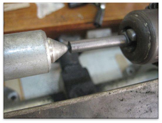
Pic.4
The motor started working with voltages of 115 VAC or 90 VDC, being that with DC it has a stronger torque. These were the best values to get the motor rotating without vibration, although the indication was 220 V, but I did not risk to go that far because there were some loose bearings.
Note: the motor is equipped with two lubricating cups, only one survived. This gives an idea of how things were made in those times.


Pic. 5 a,b
Here the manufacturer's name and characteristics, 220V AC, rpm and power.
III
OPERATION
The base of this machine is a 7mm thick steel plate, where all components are placed.
See Pic..6
The rotation drive is a motor A with brushes A1 and A2. Being the case that it is intended to reverse the rotation of the motor, it is useless to change only the polarity; the polarity of the stator has to be changed in relation to the rotor. Everybody knows this.
The motor makes worm gear A3turn, which reduces the speed of the gear B, turns the shaft where the cam mand gear P is mounted.
The movement of the wheel P, can be multiplied or reduced and goes to the gear S through the gear C. As can be seen Fig.8, there is a set of wheels that allows many combinations.
Gear Cis changeable, thus allowing for the different sizes for wheels Pand Sto be adjusted. GearSis fixed to gear D1 that engages D2at an angle of 90 º. Gears P, Sand D1are removable with nuts fand g.
Gear D2can be freed from the common shaft -coil /turns counter- by means of the red screw n~
The coil engages into position i. There are several accessories for different types of coils.
The oscillating movement comes from the cam m that moves the pieces h,p,n,kand j, these last two are kept in place by two fixed shafts that are fixed into two L shaped plates on each end.
The moving parts move together with the cam by an adjustable spring. The cam, when rotating, makes pressure on a bearing of shaftpthat makes bar nmove, which, in turn, moves piece k and the wire distribution arm.
Nut h allows the amplitude of piece p to be adjusted and thus the width of the coil,kcompensates the angle of the bar due to the regulation of hand j adjusts the position of the arm to the position of the coil.
All these parts can be better seen in the assembly process

Pic. 6
IV
ASSEMBLING THE WINDER
Every piece required a lot of cleaning and patience to remove all corrosion, specially from the shafts, because this machine must have been put aside in a damp place in Radiolux.
As it was said before, the base is a very heavy steel plate of some 7 mm thickness, that resisted to let go all the accumulated rust. All the screws that fastened the parts had to be replaced by new brass M4 (bought in Casa dos Parafusos).
Follows the sequence of the assembly of the machine.

Fig.7

Pic.8

Pic.9

Pic.10

Pic.11

Pic.12

Pic.13
V
THE PROBLEMS
Once the assembly of the machine was finished and the motor started, I realized immediately that the distribution of the wire was not uniform. The cam that makes the back and forth movement of the arm was not correct, and that made an irregular distribution with smaller spaces among turns on the first half of the coil, and wider spaces among the other turns.
This results in a lot of wire on the first half of the coil and not enough on the other half. The arm must travel uniformly back and forth through the whole length of the coil.
Probably, this is why the machine had been put aside.
And this enforced me to make new cam as I will explain latter.
After the new cam and all other parts were assembled, I had to make and adjust others, such as:
-Wire guide
-Wire tensioner and support
-Turns counter (adapter)
-Tensioned spring for the wire distribution coil
-Arm that follows the cam
-Bearings
-Cleaning and lubrication of moving parts
VI
THE RF COILS
May I insist a little more on the RF coils, some of these, mainly the older ones have a special type of honeycomb. And why?
I leave here this matter to someone else to explain more and/or correct me.
The honeycomb coils have been always of much interest for me but now they became an actual challenge for me. On the RF coils one turn of a coil (solenoid) must keep a distance from the turn before and the turn after in order to minimize the capacity component and thus increase the quality factor Q (coil with a high induction L and a low C capacity and low R ohmic resistance).
Thence the space among the turns. Another procedure is to avoid the usual skin effect inside conductors where the AC magnetic field inside the wire pushes the conduction path to the surface of the wire. This effect is directly proportional to the square root of the frequency, and this fact reduces the useful cross-section of the conductor, thus increasing its ohmic resistance R and reducing its factor Q. wikipedia.org/wiki/Skin_effect
To minimize this peculiar skin effect Litz wire is used. This wire is made of several insulated wires bundled together, thus increasing the total section of the conductor and so we can increase the coil factor Q by reducing the its ohmic resistance R.
There are two ways to wind the wiring in honeycomb:
One is by the sinusoidal movement of the arm/wire along the width of the coil (see picture 14 red line).This way the relation between the movement of the arm and the rotation of the coil is uniform in relation to the sine of the angle of the rotation of the coil.
It is slower at 180º and 0/360º at the change of direction of the arm, and faster at 90º and 270º.
Another way is by the movement of the arm/wire proportional to the rotation of the coil, which is, for each millimeter of displacement of the arm there is always a fixed number of degrees of rotation of the coil. This grants a triangular distribution of the wire through the whole width of the coil (see picture 14 black line)
.jpg)
Pic.14
VII
THE CAMS
As explained, two types of cams should be required (in order to transform the rotation of the coil into the oscillation of the arm), the first circular shape, the second in a heart shape. The first makes a sinusoidal movement of the wire over the coil, the other a triangular movement over the coil.
According to what I have seen on the Net the second should be the more correct one, and this is why I prepared the new cams, three in all.
The first circular cam (cam B), has the possibility of routing variation with a cam-center variation. Wrong, the center should be fixed. The second one (cam C) is in shape of a heart, but is too big. The third one (cam D) also in a heart shape, is smaller and OK. The size of the cam is connected to the width of the coil. In my case, the coil that I wanted to make was less than 4 mm wide, hence the need for a smaller third cam D, but for this thread I will shall use the second for a wider coil.
Useless to say that all work has been done manually either in steel and brass with very precise measurements.
For the working on the C and D cam I used vectorial drawing type Autocad on a large scale and later reduced to the desired scale.
The drawing was done with 12 concentric circles, the circumferences are intercepted from the center by radial lines every 15º. I started on the 0º radial line and at the interception of the smaller circle I marked one point. On the next 15º radial line I marked another point on the interception to the second circle, and so on, until the 180º radius with the bigger circle. Then I inverted the sense and returned to the 360º/0º radial line at the first point of the smaller circle. Joining the points with a black line, I got the form of the cam.
The cam can be seen in picture 15
A-The older one where neither the center nor the shape were correct.
B-The first made, circular with a variable center.
C-The second made in a heart shape, but too big.
D-The final one, smaller, with a similar shape to C

Pic.15
VIII
THE PITCH LENGHT
Another thing was to figure out how to handle together the different available gears P and S (see picture 8). All were numbered with their number of teeth. Of those already existing in the machine, P and S were easily removable.
Concerning the Primary wheel and the Secondary wheel (see picture 6 and 11), I realized that if two wheels P and Swith 100 teeth were mounted and engaged, thenthe wire comes from point A (red line on picture 14b) -0º on the coil, crosses to the other side of the coil to point B (red line on picture 14b) at 180ºand comes back to the same point A.
But if I put one wheel P of 90 teeth and another S of 100 teeth, (arm moves faster then coil shaft ) thenthe wire goesthrough the same track but arrives sooner + 18ºto point B' and 36º further to pointA' (green line picture 14b). Then at the end of 10 turns, the wire will be again at the same original point A .
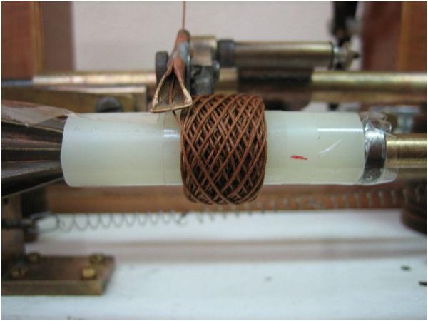
This coil should have been made with Litz wire, but in my tests I used ordinary cotton string...
This has been my theoretical approach, and once I had available this winding machine (Thanks Zé) and a lot of cotton string, why not try more experiments? In the next paragraph, the TEST COIL.
So I realized:
1ºThe relation between wheelsP and S like 100-»100,120-»100 and 120-»40, results respectively in one solenoid for one turn, two and three solenoids per rotation respectively.
2º The relation between the number of teeth cannot be a whole number such as 100-»100,120-»60- or 120-»40.This way, the wire gets superimposed. Same with Lissajous curves when n is 1:1 , 2:1 or 3:1 and so on .
3º Wheel P must be bigger than S in order for the wire go slowly from one side to other.
4º The relation between wheels corresponds to the space between turns.
5º To a relation of P=100 and S=95 corresponds 18ºdegrees, one turn.
6 ºTo a relation of P=100 and S=97 corresponds +- 9º degrees. one turn.
7º On the relations near P=120 and S=40 the coil becomes more tighter ( n=3:1).
8º The dimension of coil LxD ( L Large and D Diameter ) and is proportions , define the crossing of wire for same relation P an S, decrease S reduce the pitch .
I leave here a challenge to other possible relations between wheels.
IX
Testing Coil

Pic.16
P120-»S90 – n=1,33 4turn. -a´ 1º turn.+120º -a´´2 turn.+ 240º -A 4 turn

Pic. 17 - P120-»S90 30turn.
Pic.18 - P120-»S112 100turn.

Pic.19 - P120-»S112 300turn.

Pic. 20 - 100-»90 10turn.

Pic. 21 - P120-»S80 10turn.

Pic. 22 - P120-S40 18turn.

Pic. 23 - P100-»S50-100turn.

Pic. 24 - P114-»S40-100turn.
X
Simulating Coil Turns With Lissajous Curves
When I try to explain Pic. 16 I have some difficulty.
I realized if I use the principle of Lissajous I have a good analogy.
Then I use my Classic HP200CD , HP3301B, HP3515B and TEK2445 for the analogy .

Pic. 25
The HP200CD sinusoidal generator simulated the wheel S, with the Sy Frequency. (S for rotation of coil and y for coordinate y). The HP200CDtakes some time to set to 100Hz with 5 digit precision, but after setting it, it does not change (it's stability is amazing), but it does not have Triangle Wavefrom output sorry, I do not have a second generator with Triangle Wavefrom output :( , If anyone wants to sell one like HP3310A for a good price, I would accept :) .
I associate generator HP3301B with wheel P and the movement of arm and the wire and is oscilloscope input x, and the HP200CD is input y to the oscilloscope, (I use the notation Px,Sy) .
The 3301B is the second generator with adjustable Frequency Px I use the function Triangle wavefrom, the same shape of the movement of cam.
The HP5315B is the frequency counter to read Frq. Sy or read 2nd Frq.Px or ratio between the Frq´s.
The TEK2445 is our oscilloscope in x/y mode.
NOTE: There is one inversion of notation between the honey-comb machine for P and S teeth and the HP´s Frequencies Px and Sy. Because of the relation P120-»S90, S doesn’t reduce speed but increases it, then Sy takes higher speed and Px lower. P=Sy, S=Px

Pic. 26a The HP200CD is Sy120 and 3310B Px90

Pic.26b Sy120 Px90 n=1,333 4turn
brown up wire, with back white wire, red transition top and bottom points
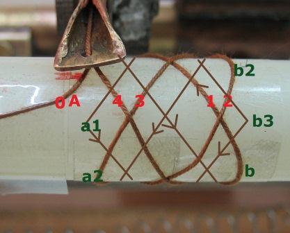
Pic. 26c
P120-»S90 n=1,333 4turn, note 0A and 4 (end of 4ª turn) same start and end, 3x0,33=1 or 3x120º =360º.

Pic. 26d – P120 –S90 n=1,333 30 turn.
.
Pic. 27a The 3310B isSy120 and HP200CD Px112

Pic. 27b Px112 Sy120 n= 1,07

Pic. 27c – P120-» S112 100 turn.

Pic. 27d – P120-» S112 n= 1,071 300 turn.

Pic.27e Ratio A/B 1,07

Pic 28a Sy120 - Px80 n=1,5

Fig. 28b – P120 – S80 n=1,5 10esp.

Pic.29a Sy120 - Px40 n=3

Fig. 29b - P120 - S40 n=3 18esp

Pic. 30a Sy100 Px50 n=2

Pic. 31 - P100-S50 n=2 100esp.

Pic. 32a Sx114 Py40

Pic. 32b– P114-»S40 n=2,85 10turn.
XI
Final remarks
I think I have demonstrated that Lissajous curves can be used to simulate honey comb wiring (with a second triangular signal generator we would have on the oscilloscope straight segments and not sinusoidal segments.). To reinforce what I said before, when the relation between the frequencies Sy and Px (corresponding to number of teeth) is a natural number such as with n=2 orSy100/Px 50 Pic.23a ( there is one vertex on the top side of the coil ), with n=3 Sy100/Px 33 pic.22a (there are two vertices) and with n=4 Sy100/Px25 (there are three vertices) and so on.
For these relations n=xx (natural number), the turns of the wire superimpose themselves ,and it has to be among these values that a quotient has to be found between the frequencies (or the number of teeth). The bigger the dividend, the more perpendicular the wire will be in relation to the shaft of the coil.
At the limit, we would have a null wire step, or before that, the adjacent wire step would be the thickness of the wire and we would have a conventional winding machine without the honey-comb wire spacing. As we increase axle velocity Sy and reduce arm swing Px, we reduce the wire stepping. This is to say, S=Px with few teeth and P=Sy with many teeth.
If we made the quotient of Sy100/Px105, or a/b and b greater than a, then the quotient is between 0 and 1, - 0,95 one 1/20 there will be 18 degrees to the vertex on the top perimeter of the coil and on this machine is S105 teeth and P100 teeth. For the HP's the 200CD 105Hz and the 3310B 105Hz.
For coils where the length is more than the diameter, P can be multiplied by «n» and a difference of five teeth can be maintained, which would give 205 or 305.But we do not have these wheels, so we reduce S to 40 and make P 125 (3x40+5).This way, we keep the number of vertices on the sides of the coil, but reduce the speed of the advance of the wire over the coil, that is, the wire distribution arm runs more slowly, so the wire stays more perpendicular to the shaft of the coil.
I finish my study about the use of the teeth wheels, with a difference of one teeth and two Pic 33,34 and 35, simulate with the HP's (beautiful machines. The HP 200CD from 1953!! this one is from 1965, prefix 605-xxx) between 100Hz and 101Hz or 102Hz respectively, the number of lines visible on the photos results from the time of exposure.

Pic. 33 - Px101Hz Sy100Hz

Pic.34 - Px102Hz Sy100Hz

Pic.35 - Px102Hz Sy100Hz
Many Thanks for Mr. A.B. Regada without him, I would not have gone as far, and Mr. Joe Sousa with proof-reading of the English translation and his technical expertise.
Lisboa,
Hernâni Capela, at 15 November de 2012
To thank the Author because you find the post helpful or well done.
HONEY COMB WINDING MACHINE
Hello,
Well, after these years I received from the owner Zé, this photo of the Honey Comb Winding Machine
Mr. José Manuel (Zé) prepared her more to present in a museum, I had prepared her to work.
Best Regards
Muito Bem Hajam a Todos
Hernâni Capela

foto inserted by DR
Attachments:- IMG-20210505-WA0003 (238 KB)
To thank the Author because you find the post helpful or well done.