Lighting up dark Eye tubes
Lighting up dark Eye tubes

Fellow radiophiles:
Noted Cathode Ray Tube historian Peter Keller had an interesting short note in the June 2012 issue of the "Tube Collector" bulletin.
Peter A. Keller is well known for his book: The cathode-ray tube: technology, history, and applications. New York: Palisades Press, 1991. ISBN 0-9631559-0-3.
Peter Keller in the June 2012 issue of the "Tube Collector" bulletin as edited by TC editor Ludwell Sibley:
"Your article on restoring magic eye tubes was interesting and fits my observations. I ran some experiments with CRT aging in the 1960s. It rapidly became apparent that phosphor aging was primarily a function of current density (Coulomb aging). Even though a constant power density was maintained, aging occurred much faster at high current and low voltage than low current and high voltage. I would expect the same for magic eyes. Operating the tube at the highest anode voltage and reducing the cathode current would reduce aging, and since brightness usually increases rapidly with small increases in anode voltage, it permits even greater reduction in current for longer life. This would probably work best with a tube having completely separate amplifier and indicator sections or something like a 6AF6. I believe the reason for Coulomb aging is that as the voltage is increased there is greater penetration into the phosphor and the heating of the phosphor and light emission occur over a greater volume of the phosphor crystals rather than just the surface. Also any surface contamination such as from barium becomes less of a factor since the electrons more easily penetrate the contamination layer."
----------------
Email from Peter Keller dated 06:09 PM 8/7/2012:
Joe,
A little further information concerning electron-ray /tuning indicator/"magic-eye" tubes.
The effect of increasing the light output by raising the anode voltage is not linear. Doubling the voltage will usually more than double the light output. This is due to surface aging and surface contaminants including the graphite used to prevent phosphor charging at the relatively low operating voltages of electron-ray tubes. At low voltages, without the conductive coating the secondary emission ratio of the phosphor will cause it to charge negatively toward the cathode voltage and thus repel additional electrons.
Above the first crossover voltage (typically 100-300 volts for Willemite) where the secondary emission ratio is 1.0, the phosphor charges positively toward anode potential. This continues until the second crossover voltage is reached (several thousand volts for willemite) and further increases in light output are negligible due to negative charging of the phosphor. The latter effect is important only for high-voltage cathode-ray tubes.
Higher voltages allow deeper penetration of electrons into the phosphor crystals where heat dissipation is better and crystal purity is likely greater. Of course, some of the light emitted within the crystal is absorbed by having to pass back through it and lost due to the index of refraction at the crystal surface/vacuum interface. As you can see, there are many factors effecting light output from the phosphor.
Phosphor aging is due to two causes, both occurring whenever an electron beam is absorbed by a material. The first is thermal damage which is non-reversible. The second is X-ray darkening which is reversible with baking. The former is probably the dominant factor in electron-ray tubes.
I am glad you found my notes helpful. You are correct, controlling the heater seems like the only practical way to control the anode current.
pk
------------------ Phosphor types in eye tubes
At 03:39 PM 9/3/2012, Peter Keller wrote:
I can't see any problem with running the cathode temperature-limited. Even
if it shortens life a little you still got more use out of it. You will have
to increase heater voltage as it ages, though.
No problem quoting me on the website although I would like to also see TCA
use it if they want.
pk
Peter's experiments showed that phosphor decay was a function of beam current but not a function of target voltage. Increased target voltage also increased brightness disproportionatelly, thus allowing for greater reductions in beam current.
Peter's note also suggested that a higher voltage would use a greater volume of the available phosphor due to deeper penetration of beam current at higher target voltages. This made me wonder if old round Eye tubes with their very short lived P1-Phosphor Willemite phosphor could be made to glow again with a raised target voltage and reduced beam current.
I measured 10 different round Eye tubes and all the tubes that were dark at the nominal 250V operating voltage glowed brightly again with the target at 500V. Note that 500V operation is not a rejuvenation effect; subsequent operation at nominal 250V is unaltered.
I show here the EM34, 6E5 and 6T5 as representative examples of the 10 measurements. The full set of 10 photos of eye tube targets is in pdf format. The photos were taken with a Canon S90 digital camera in full manual mode to allow for comparison of brightness levels. The exposure duration is shown for each tube. All photos were taken in complete darkness with ASA=400, F3.5, Macro=6mm at a distance of 2 inches between lens tip and the tube target. All eye tubes were biased with <-25V at the control grid to close the eye pattern. Note how the very bright EM34 was shot with one quarter of the exposure (1/80s) as compared to the 6E5 and 6T5 which were both much dimmer and shot for 1/20 seconds. The 6T5 on the third column shows a mottled pattern. A magnet near the 6T5 rotated the mottled pattern, thus proving that the mottling was projected from a deteriorated cathode.
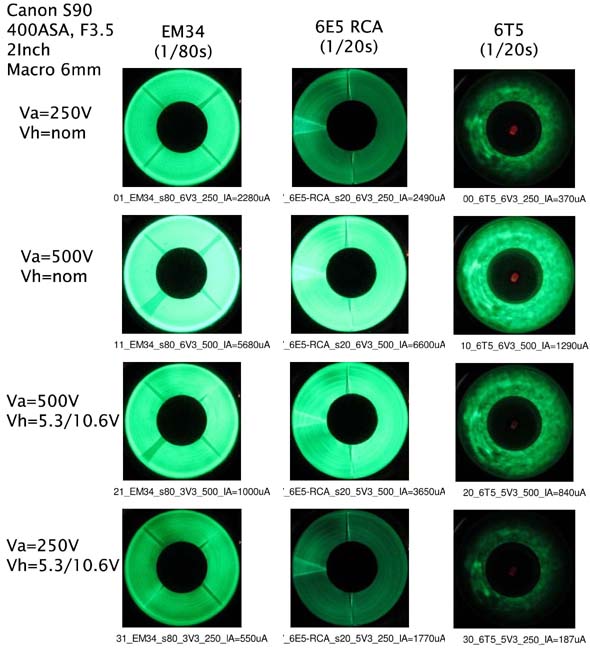
The first row shows the glow under nominal operation with 250V at the target. The EM34 is new old stock, but the 6E5 and 6T5 are both used tubes. The 6E5 was still usable with nominal target voltage, but the very rare and expensive (~$100USD) 6T5, which was used in late 1930's Zenith consoles, had a faint glow that could only be seen in complete darkness. Also note that the nominal target currents for this class of eye tubes is 2-4mA, but the 6T5 also had reduced emission of only 370uA, probably because this tube stayed in service long after it went dark. (See Peter's notes above explaining the various phosphor types. The EM34/EM35 types are likely to have newer phosphors other than P1 Willemite).
The second row shows increased brightness with 500V at the target. This increased brightness was noticeable for the brighter tubes, but it was a dramatic improvement in glow for very dimm tubes like the 6T5 shown here.
The third row shows that much of the brightness is retained even when emission is manually reduced with a 1V reduction in heater voltage from 6.3VAC to 5.3VAC. In the case of the 6T5, there would would be little need to cut back it's already weakened emission.
The fourth row shows the moderate effect that reduced emission current under reduced heater voltage has on brightness.
These photos show that brightness is indeed a much stronger function of target voltage than target current, and a dark eye tube can be made to glow again, if the target voltage is doubled.
Voltage doubler for Eye Tubes
In correspondence on this topic with Radio Age editor Ed Lyon, he encouraged me to build a circuit that I suggested as a possible plug-in eye tube adapter circuit that doubles the target voltage.

The circuit uses the modern solid state equivalent of an old fashioned vibrator to convert the available 250VDC target voltage to a chopped 250VAC to drive a standard cap-diode voltage doubler. The chopper is implemented with a dual solid state relay from Vishay part number LH1532FP. This solid state relay can withstand 350V in the OFF state and has 20 Ohms resistance in the ON state and generates on RF interference with it's low turn-ON-OFF speeds of 100us. The control LED's of the solid state relay are wired in anti-parallel to close each half of the SSR on alternate half cycles of the 6.3VAC input. The 1ms stops in the rise and fall of the 250V chopper output occur when both halves of the solid state relay are open, thus insuring break-before-make action.
Solid state relay substitution with a reed relay - The Vishay LH1532FP solid state relay may be difficult to find.
 One alternative is to use a reed relay as a chopper. Modern reed relays can be very long lived. I have used COTO-0210 reed relays as low power chopper substitutes for tube opamps and have gotten over 2 years of continuous service. Sometimes the relay coil diode is already included with the relay as an inductive kickback snubber. Current limiting resistors >1k are necessary in series with the chopper ouput to limit peak charging currents passing throught the reed contacts.
Heater voltage dropping resistor - The lower left of this schematic shows a series string of 3 nearly binarily weighed resistors that form the heater voltage reduction series resistor that varies from 0 Ohms to 8.5 Ohms. The value of the net series heater resistance is programmed with three shorting jumpers and should be adjusted empirically to obtain less than 1mA of target current. R12 serves as a handy current shunt to monitor target current, but bear in mind that this resistor has both terminals elevated to 500VDC. 1V drop at R12 indicates 1mA of target current.
Series heater AC/DC sets - In AC/DC sets with eye tubes with their heaters in a series string (i.e.: Automatic 850 or VEF LM507 ) , a resistor should instead be added in parallel to reduce the drop across the eye tube heater. AC/DC sets running from 117VAC will have a generally low plate voltage around 120VDC. In this case, one or two extra cap-diode stages would be needed to triple or quadruple the target voltage. One of these optional stages is shown at the upper-right of the schematic.
Gain doubling - One problem with doubling the target voltage is that the deflection sensitivity is cut proportionally in half. An extra gain of 2 is needed to overcome this loss of deflection efficiency. The MPS4250 PNP emitter follower Q1 at the cathode of the 6E5 eye tube applies positive feedback from the triode preamp plate to double the net gain via the triode. The PNP needed a low voltage negative bias supply around -4V shown at in the center of the lower half of the schematic. R5 and R6 provided the needed feedback path with an attenuation that roughly matches the unaided gain of the triode. R6 is adjusted to obtain a positive swing at the cathode that matches the negative swing of the control grid. After adjustment of R6 the cathode and control grid swing equal amounts in opposite directions, thus doubling the net swing "seen" by the control grid. C6 simply prevents oscillations. An alternative method to adjust R6 is to adjust it to close the eye pattern when the rated eye-closing control grid voltage is applied. This value is -8V with 250V at the 6E5 target. If the value of R6 is adjusted too high, there will be too much positive feedback, and the eye tube may stick in the closed deflection position. Keep in mind that the triode preamps in eye tubes often have a remote cutoff characteristic, which implies a varying voltage gain as a function of applied control voltage and the 2x factor gain boost will not be constant.
The MPS4250 PNP has a beta around 450, which keeps base current low that would offset the voltage at the R5-R6 feedback network. A lower Beta=150 2N3906 could be used, but perhaps a 2N3906 Darlington pair should be configured with the input collector returning to the -4V bias supply.
Operation with input voltages substantially less than 250V may require some reduction in the value of R7=470k to properly offset the Vbe drop of the PNP.
Power drain - The chopper/voltage doubler architecture of this circuit is inherently highly efficient. When the 6E5 is unplugged, the doubler draws only 400uA from the 250V input. When the 6E5 draws 1mA from it's target, the input current is 3.2mA. The input power is 0.8W with a 0.5W load.
Plug-in Adapter Eye Tube Target Voltage Doubler


This little 6-pin plug-in adapter can be plugged into a socket of any of the 6E5 pin compatible tubes without any modification to the radio. The photos show the 6-pin 6E5, but other sockets could be used for other eye tube types. When different Eye tubes are used, the 2x gain setting resistor R6 may need readjustment as outlined above. The 2.2uF 450V silver aluminum caps are the voltage doubling capacitors C2 and C3 and the black capacitor in the center C1 is a repurposed 80uF 300V cap from a disposable flash camera. Larger values for the 2.2uF caps are OK up to 10uF, but >1k current limiting resistors should be added in series with D1 to limit peak currents through the chopper. The Vishay LH1532FP solid state relay is surface mounted directly on the foil pattern under the board and it's pins line up with the 0.1" spacing of the prototype PCB traces. Layout is not critical and the only significant dissipated heat is at the heater series dropping half-watt rated resistors that could dissipate up to 1/4 Watt. This circuit could be enclosed in a candy tin with proper insulation.
Uses for the eye tube voltage doubler - There are two distinct uses for the eye tube voltage doubler. The most obvious use is to bring a dark eye tube back to life. This is particularly useful with expensive or rare eye tubes, like the 6T5 that was used in late 1930's Zenith consoles.
The other use is as a way to increase the life of a new eye tube P1-phosphor Willemite target with operation at reduced target current, increased target voltage and reduced heater voltage. However, operation with reduced heater voltage causes a reduction in the thickness of the space charge around the cathode that protects the cathode from the impact of stray ionized gas particles in the tube. Perhaps some reduction in the life of the cathode is justified because cathodes in eye tubes greatly outlast the life of the Willemite P1-phosphor target, perhaps by as much as 10:1. So, some shortening in the life of the cathode is worthwhile to extend the life of the Willemite P1-phosphor.
Acknowledgements - Thank you Peter Keller for sharing your experience with phosphor decay, thank you Ludwell Sibley for recognizing the importance of this information for the Tube Collector bulletin and thank you Ed Lyon for encouraging me to build the Eye tube adapter.
Best regards,
-Joe
To thank the Author because you find the post helpful or well done.