Negative Resistance Oscillators

7
ID: 239936
Negative Resistance Oscillators 
17.Dec.10 22:11
50
7

Dietmar Rudolph † 6.1.22 (D)
Articles: 2492
Count of Thanks: 15
Dietmar Rudolph † 6.1.22

Occasionally radio sets use mixers with negative resistance oscillators like e.g. the model "Stassfurt Imperial 4W" from 1933/34. The schematic of its mixer part shows such an oscillator.

The oscillator LC circuit only has two connections to the valve. It has no tap or tickler coil. Oscillations will only the occur, if the tube provides a negative resistance which compensates the losses in the LC circuit. The negative resistance has to be smaller than the positive resistance of the LC circuit.

A description of this kind of oscillator is found in "Terman, F.E.: Radio Engieering, McGraw-Hill, 2nd ed.,1937"


Negative Resistance

A convenient method of obtaining a negative resistance is to connect a pentode tube as shown in Fig. 83.1


Here the screen-grid and plate electrodes are both positive, and the suppressor is sufficiently negative to produce a virtual cathode between the suppressor and screen. A high resistance is placed between the suppressor and its bias potential, and the suppressor and screen electrodes are tied together with a by-pass condenser. With this arrangement the screen-grid circuit offers a negative resistance to alternating currents. This is because the screen and suppressor electrodes are at the same potential with respect to alternating currents, and, if the potentials of both electrodes vary together, the current to the screen will decrease with increasing potential, and vice versa. The reduction in screen current comes about because the screen current consists largely of electrons that have returned from the virtual cathode produced by the negative suppressor. As the suppressor-grid potential increases, more electrons are drawn from the virtual cathode to the plate, leaving fewer to return to the screen and hence reducing the screen current. The magnitude of the negative resistance obtained in this manner can be controlled by varying the control-grid potential. With ordinary tubes values as low as 3000 or 4000 ohms are obtainable.

A number of other negative resistance arrangements using vacuum tubes have been proposed but none of these except the magnetron, [which is discussed above,]  has had much practical use.

Negative resistances obtained from tubes can be used as ordinary circuit elements, and make it possible to achieve circuit behaviors not realizable with positive circuit elements. Thus it is possible to devise amplifiers, oscillators, etc., based upon circuits containing negative resistance elements, although none of these arrangements except the dynatron oscillator have been used to any extent.

Dynatron and Similar Oscillators Employing Negative Resistance.

The negative plate-cathode resistance of a dynatron can be used to produce oscillations by connecting a parallel resonant circuit in series with the negative resistance as shown in Fig. 198a.


Such an arrangement will oscillate provided the negative plate resistance is less than the parallel resonant impedance ofthe tuned circuit. Also, if the grid bias is such that the negative resistance is just barely low enough for oscillation, the frequency stability with respect to tube conditions is extremely high and the oscillation is practically sinusoidal. Such oscillators are sometimes used for laboratory or test oscillators, and are particularly satisfactory when combined with automatic amplitude control so as to maintain the tube conditions on the threshold of oscillation at all times, as discussed below.

Negative resistances obtained in other ways can be used in similar manner to produce oscillations. Thus the oscillator of Fig. 198b employs the negative resistance arrangement of Fig. 83, and has the advantage over the dynatron in that negative resistance obtained by secondary emission is relatively unstable at times.

Synchronization between oscillations related by harmonies is discussed in the paper by Isaac Koga, A New Frequency Transformer or Frequency Changer, Proc. I.R.E., vol. 15, p. 669, August, 1927. Also see U. S. Patent 1,527,228 issued to Schelleng; and J. Groszkowski Frequency Division, Proc. I.R.E., vol. 18, p. 1960, November, 1930.


IFor further discussion see F. E. Terman, "Measurements in Radio Engineering," 1st ed., pp. 287 290, McGraw Hill Book Company, Inc.


'For further information about the dynatron and its uses see Albert W. Hull, The Dynatron, a Vacuum Tube Possessing a Negative Resistance, Proc. I.R.E vol. 6, p. 5, February, 1918,

2 See E. W. Herold, Negative Resistance and Devices for Obtaining It, Proc. I.R.E., vol. 23, p. 1201, October, 1935.
 
The dynatron is essentially a tetrode operated with the plate less positive than the screen and having appreciable secondary emission at the plate. Thererfore, the negative resistance of the dynatron results from secondary emission at the plate and is dependent from the material of the plate and may be different from tube to tube. The lowest negative resistance obtainable from tetrodes used as dynatrons is about 10kΩ to 20kΩ.
 
A similar oscillator, using a pentagrid converter valve instead of a pentode is suggested by "Langford-Smith, F.: Radio Designer's Handbook, 4th ed. Iiffee, 1953"
 
 
(vi) Negative transconductance oscillators

 
Several types of negative transconductance oscillators have been suggested using r-f pentode valves. These circuits have a negative bias on the suppressor grid and rely for their operation on the fact that, over a particular range of negative voltage on this grid, the suppressor-screen transconductance is negative. With suitable operating conditions a positive increment in the negative suppressor grid voltage will allow the plate current to increase and the screen current to decrease even when the screen voltage is increased ; the changes in screen and suppressor voltage being approximately equal. The screen and suppressor are coupled together by means of a capacitor, and the tuned circuit is connected in a suitable manner between plate and screen. Detailed descriptions of this type of oscillator can be found in Refs. 7 and 23. Circuits using this arrangement with pentode valves are not very convenient since the negative transconductance is only of the order of -250 micromhos. Since this oscillator is a two terminal type it is often a very convenient arrangement ; one particular example is its use as a beat-frequency oscillator in a radio receiver. A particular form of the negative transconductance oscillator (Ref. 13) – which employs, also, the principle of electron coupling – using a pentagrid converter valve (e.g. type 6A8, but not 6SA7, 6BE6 etc.) is shown in Fig. 24.7. The negative transconductance is brought about as follows. Electrons moving towards the plate are turned back to the inner screen (G3) and the oscillator anode (G2) when the control grid (G4) has a more negative voltage applied to it. The net effect of an increase of negative voltage on the signal grid is to increase the current to the oscillator-anode and to grid G3.


Any increase in the current to G3 is practically offset by a decrease in the current to G5, the outer part of the screen grid, and the result is that the screen current remains fairly constant for wide variations in signal-grid voltage. The variation in oscillator-anode current, however, is equivalent to a negative transconductance between the control grid (G4) and the oscillator-anode (G2). In type 6A8 this amounts to about - 400 micromhos. Because of this negative transconductance it is possible to create an oscillatory condition by coupling G4 to G2, provided that the rest of the circuit is suitably arranged.

The circuit of Fig. 24.7 has been used at frequencies up to 18 Mc/s. It has also been employed in several types of communications receivers (having intermediate frequencies of from 255 Kc/s to 3 Mc/s) as a beat-frequency oscillator and has given very good results as regards stability of operation, particularly when temperature compensation has been applied to the tuned circuit.

It is near enough, for practical purposes, to take the frequency of oscillation as being f0 = 1/(2π[L0C]½).

See also "Dual Control Pentodes"  and the schematic with the 6DT6.

Regards,

Dietmar

To thank the Author because you find the post helpful or well done.

 2
The Transittron Oscillator 
18.Dec.10 12:25
50 from 21325

Dietmar Rudolph † 6.1.22 (D)
Articles: 2492
Count of Thanks: 21
Dietmar Rudolph † 6.1.22


This text about the Transitron Oscillator and the characteristic of the pentode is compiled from “K.R. Spangenberg: Vacuum Tubes, McGraw-Hill, 1948” and “Eastman, A.V.: Fundamentals of Vacuum Tubes, McGraw-Hill, 1949”.
 
Negative Transconductance Oscillator (Transitron Oscillator).

A principal disadvantage of the dynatron oscillator is its dependence upon secondary emission, which varies considerably with age in any given tube. Similar oscillations are obtainable without the need of secondary emission by operating a pentode in such a manner that the transconductance between two of its grids becomes negative. A tube operating in this manner has been termed a transitron oscillator.
[Cledo Brunetti, The Transitron Oscillator, Proc. IRE, 27, p. 88, February, 1939.]

Negative Screen-grid Resistance of a Pentode.

The screen grid of an ordinary pentode exhibits a negative-resistance characteristic if it is connected to the suppressor grid in such a way that an increase in screen-grid voltage is accompanied by an equal increase in suppressor-grid voltage. This is evident from the curves of Fig. 20.19.


This family of curves shows the I2-V2 characteristics of a pentode for various values of V3 where the numerical subscripts refer to the grid number in order from the cathode to plate. The solid curves show the I1-V2 characteristics. As the No. 3 (suppressor) grid is made more negative, the No. 2 (screen) grid current decreases. If the No. 2 and 3 grids are connected so that there is a constant difference of potential between them, the dotted curves shown in Fig. 20.19 result. The screen current decreases as the suppressor grid is made more positive; for the latter then transmits a greater fraction of the space current that approaches it, and as a result less current is returned to the screen grid. This decrease in reflected current more than offsets the increase in directly intercepted space current that is taken on by the screen grid as a result of its more positive potential. The two dotted curves of Fig. 20.19 are for differences of No. 2 and No. 3 potential of 54 and 90 volts, respectively. The magnitude of the negative resistance made available by this means is of the order of 3,500 ohms, which is considerably less than that obtainable from a dynatron, which is usually of the order of 10,000 ohms. The region of negative resistance is limited at low voltages by the condition that the suppressor grid is returning all the electrons which approach it and beyond this condition the suppressor grid has virtually no influence. Correspondingly, the region of negative resistance is limited at high voltages by the condition that the suppressor grid is passing all the current which approaches it and so again loses control.

In actual applications the screen and suppressor grids are separately biased and fed through separate resistors but are coupled by a large capacity connected directly across the tube leads. This means that the No. 2 and 3 grids are connected together as far as voltage variations are concerned over a large band of frequencies. The negative-resistance characteristic is available from low audio frequencies, dependent upon the size of the coupling condenser compared with the size of the resistors in series with the electrodes, to frequencies of the order of 60 mc, at which transit-time effects disturb the relations.

With proper connections the negative screen resistance of a pentode can be made to furnish either sinusoidal or square waves. Likewise, trigger and flip-flop characteristics can be made available.
 

As can be seen from the Stassfurt Imperial 4W from 1933/34, the transitron principle has been applied  before the name "Transitron" was created by Brunetti 1939.


Regards,

Dietmar

To thank the Author because you find the post helpful or well done.

 3
Generating and measuring Dynatron and Arc characteristics 
19.Dec.10 11:12
142 from 21325

Dietmar Rudolph † 6.1.22 (D)
Articles: 2492
Count of Thanks: 15
Dietmar Rudolph † 6.1.22

 In the book „Rothe, H.; Kleen, W.: Elektronenröhren als Schwingungserzeuger und Gleichrichter, AVG, 1941“ a description is given how to generate and measure Dynatron and Arc (Lichtbogen) characteristics.

First a Dynatron characteristic realizable with a hexode AH1 is presented, which is similar to the characteristic of a pentode (Fig. 20.19 in Post #2).

The AH1 is the successor of the RENS1234 hexode.  In Fig. 11 a schematic how to measure the Dynatron characteristic is presented, and Fig. 13  shows how to measure an Arc (Lichtbogen) characteristic.


The Dynatron characteristic measured according to Fig. 11 is shown in Fig. 12. The point A corresponds to a voltage U4 = 0.

The Arc characteristic measured according to Fig. 13 is shown for a RENS1234 in Fig. 14. Actually, the characteristic contains two jumps, because it is physically impossible to have 3 amplitude values at the same time.

Historically interesting  is the Negatron from SCOTT-TAGGART [Scott-Taggart, J.: The Negatron, Radio Rev. 2 (1921) p. 598]. This high vacuum tube has a Thungsten filament of small diameter and a plate A1 on one side, and a grid G and another plate A2 on the other side. The principle of its operation is based on the saturated cathode current. If A2 draws more current, A1 will get less, resulting in a negative characteristic.

A Negatron circuit for the production of continuous oscillations is given in Fig. 147.

See also "Selbstschwingender Mischer mit Transitron-Oszillator".

Regards,

Dietmar

To thank the Author because you find the post helpful or well done.

 4
Scott-Taggart Negatron 
21.Dec.10 19:40
242 from 21325

Dietmar Rudolph † 6.1.22 (D)
Articles: 2492
Count of Thanks: 12
Dietmar Rudolph † 6.1.22

The Scott-Taggart Negatron oscillator from 1921 can be seen as the predecessor of the Transitron oscillator. A comprehensive description is given in "Scott-Taggart, J.: Thermionic Tubes in Radio Telegraphy and Telephony, 2nd ed., Iliffe, 1924".

The Negatron uses the saturation of the cathode current of a special diode-triode system, while the Transitron has a virtual cathode due to space charge in front of the last grid. So far, the physical effects are different, however both concepts produce a Dynatron characteristic without the need of secondary electrons.

The negatron, one of the present author's inventions, is a thermionic tube having two flat anodes, one on each side of a filament. Each anode is connected through an anode battery to the filament so that the electrons emitted by the filament, when it is heated to incandescence, are distributed fairly equally between the two anodes. A control electrode, which may be a flat grid (or sometimes a straight wire acting as a grid), is also arranged within the tube between the filament and one of the anodes. This latter anode will be called the "diversion anode," while the first one will be called the "main anode." If we suitably arrange the relationship between the electron emission and the anode voltages, we may make the sum of the two anode currents approximately equal to the electron emission. In other words, a saturation effect is obtained. Under these conditions, if we make the grid more positive with respect to the filament, we shall divert electrons from the main anode to the diversion anode, with a consequent reduction in the current flowing in the main anode circuit. In the negatron as preferably used, the main anode is connected to the grid so that when the main anode voltage is increased the grid potential is increased, electrons are diverted from the main anode, and the main anode current decreases. Hence the negativ resistance effect.


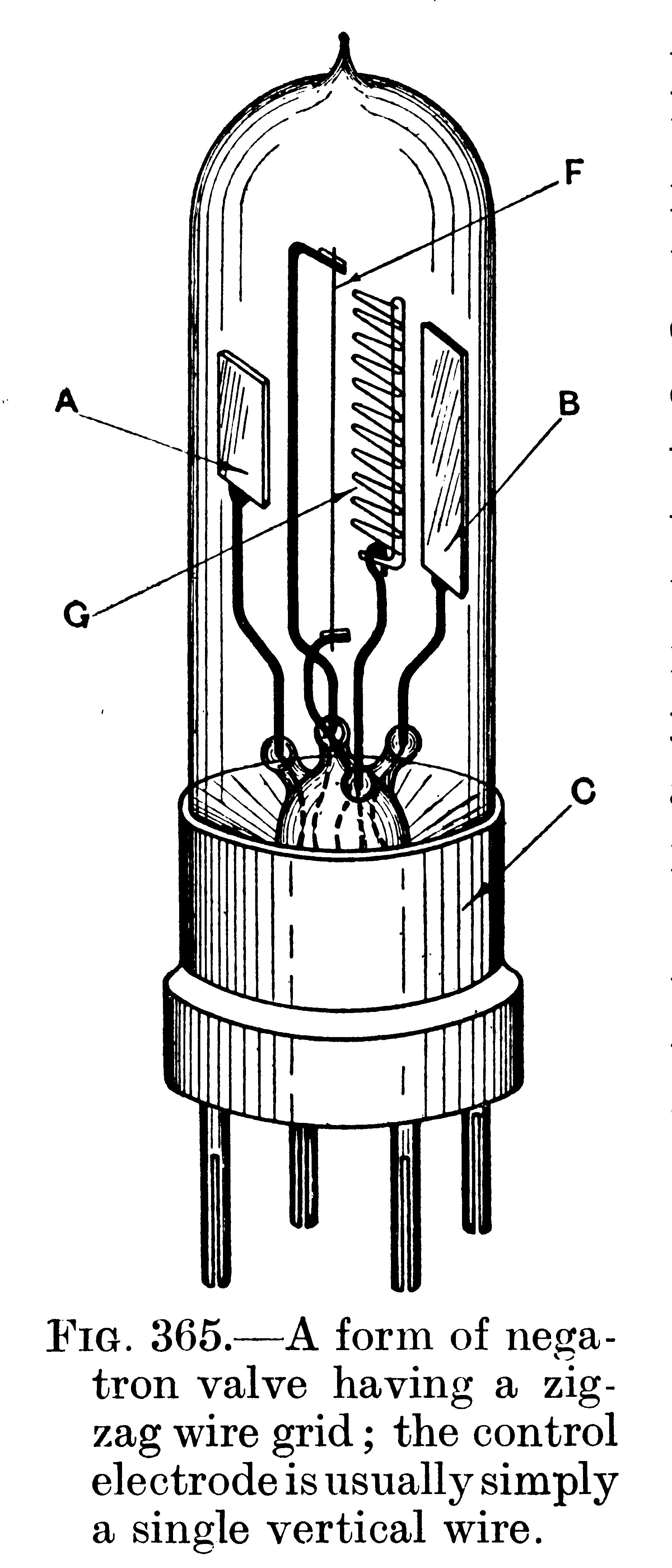
Fig. 365 illustrates the negatron tube itself. The anode on the left is the main anode (usually small), while the anode on the right is the diversion anode. Between the filament and the diversion is a flat open-work grid. A tubular bulb with a four-pin cap is preferred, the connection to the main anode being taken to the metal portion of the tube cap. A metal spring on the holder presses against and makes electrical contact with this metal portion.


The action of the negatron will be best understood if reference is made to Fig. 366, which shows a negatron connected up in one way so as to possess negative resistance characteristics. Between the anode A and the filament F is a battery B3 and two terminals I-N. Between these terminals a milliameter may, for the time being, be connected. The anode A is connected through a battery B5 to the grid G. This battery is merely connected in this position to keep the grid at a suitable potential, which is preferably slightlynegative. If G were connected directly to A, G would have a high positive potential with respect to F. Between F and the diversion anode B is a second battery B2. Both B3 and B2 are usually of about 60 volts, but their values are not very important provided that the current supplied to the filament F may be adjusted to produce the saturation effect.

Let us now see what will happen if we increase the voltage of B3. We should normally expect the current to A to increase, but as the potential of A increases so does that of the grid G. Since G becomes more positive, the current to B will increase, and this increase could be measured by connecting a second milliameter in the B anode circuit. This method of varying the current to B is, of course, well known, as it has been used in ordinary tubes since the grid was first introduced. The important fact to notice, however, is that if the current to B increases, the electrons which go to B must come from those which would have gone to the anode A. There is, therefore, a diversion of electrons. If the B anode current increases, the A anode current must decrease. Similarly, a decrease of the A anode current would always be accompanied by an increase of the B anode current. This effect is conditional on the existence of saturation in the tube. Since by increasing the potential of the main anode A we have diverted electron current to the anode B, the main anode current decreases.


There are now two effects which govern the A anode current; the increase in the A anode potential tends to increase the A anode current ; the diversion effect, however, tends to decrease the A anode current. The diversion effect greatly outweighs the other, and the result is a decrease in the main anode current consequent on an increase of the main anode potential. A decrease of the main anode potential makes the grid more negative and decreases the current to B ; the A anode current consequently increases. In this way the negatron acts as a negative, resistance.


The negatron, as described, works only when the. saturation effect is obtained. For this reason, a filament current rheostat is desirable, and the current through the filament is adjusted until the negative resistance effect is obtained. If the filament be too bright, there will be no "robbing" action; there will always be a plentiful supply of electrons around the filament, and an increase of grid potential would increase the B anode current, and the additional electrons would come from the source around the filament and not from amongst those which would have gone to the main anode. The A anode current would, therefore, be unaffected and no negative resistance effect would be obtained.


The above explanation is borne out by characteristic curves obtained with the negatron, three of which curves are shown in Fig. 367. The thick line shows the main anode current. The top thin curve shows thesum of the two anode currents. A broken line represents the diversion anode current. As the grid is always kept in the neighbourhood of zero volts, the grid current is almost zero. The grid is usually kept slightly negative, so that the grid current is zero. If this were not so, the grid current would add itself to the main anode current, and the negative resistance slope would be slightly less steep.

The curves of Fig. 367 bring out very clearly the "robbing" action which the negatron utilises. The top curve shows that the negative resistance effect is obtained while the tube is saturated. Since the total current remains constant and the diversion anode current increases (due to the control electrode potential rising), the main anode current must of necessity decrease, and this is shown by the thick line which slopes downwards. The main anode current decreases to the left of the peak because the saturation effect is non-existent (as proved by the top curve), and the decrease in grid potential produces an increase in space-charge circuit. The curve is, of course, only used along its downward sloping portion, and the oscillations will only be produced when the main anode and grid potentials are at suitable values. In practice, the grid potential is usually slightly negative, and no grid voltage adjustment is necessary.

To recount the applications of the negatron would take up too much space. The main use of it is as a generator of continuous oscillations for the transmission or reception of continuous waves. It may be used for receiving spark signals by reducing the effect of positive resistance. As a local oscillator it is exceedingly convenient, as it will oscillate on all ranges from 600 m. to 20,000 m. (the usual commercial range) without any complicated switching arrangements. The circuit arrangements which have been found most convenient are shown in Fig. 368.


These are the same as those in Fig. 366, except that the two batteries are replaced by a single one B2 of about 60 volts. The main anode A is connected through a leaky grid condenser C2 to the grid G, a resistance R1 being connected across grid and filament. This leaky grid condenser merely replaces the battery B5 of Fig. 366 for the purpose of avoiding a high positive grid potential. The filament F is heated by current from the 6-volt accumulator B, through the rheostat R2 of about 7 ohms' resistance. This rheostat is adjusted until continuous oscillations are produced in the oscillatory circuit L1C1. It is to be noted that the diversion anode circuit plays no other part in the circuit than as a path round which electrons are shunted.


It will be of interest, no doubt, to demonstrate by means of curves the fact that the negatron only oscillates over a given range of filament current. Fig. 369 shows a series of characteristic curves ; main anode currents are given for different values of filament current.


The negative resistance effect disappears completely when the filament current is above 0.575 ampere. Likewise, it disappears, for an obvious reason, when the filament current is very small. An oscillatory circuit will oscillate provided conditions are such as to come within the shaded area, and no difficulty is experienced in practice through the limited range of filament brightness.
 
Regards,
Dietmar

To thank the Author because you find the post helpful or well done.

 5
Transitron Oscillator with Automatic Output Control 
27.Dec.10 15:20
431 from 21325

Dietmar Rudolph † 6.1.22 (D)
Articles: 2492
Count of Thanks: 20
Dietmar Rudolph † 6.1.22

A Transitron Oscillator with automatic output control is presented in “Edson, W.A.: Vacuum-Tube Oscillators, Wiley, 1953”. This book is one of the rare publications devoted entirely to oscillators and their stability.
 
 
The Transitron.
A conventional pentode, when connected to produce a two-terminal negative resistance, is referred to as a transitron [Brunetti, C., “The Transitron Oscillator,” Proc. I.R.E., 27, 88-94 (1939); Muller, W.: “Transitron Oscillator for High Stability”, Electronic Inds., 4, 110 (Dec. 1945)] A suitable arrangement and the corresponding characteristic are shown in Fig. 3.3.


Because the operation is sufficiently similar to that for which tubes are designed, the governing tube parameters are normally held to reasonable tolerances in manufacture. Therefore, tubes of one type, at least from a given manufacturer, produce transitron characteristics which are quite similar.

The shape of the characteristic depends upon the action of the suppressor grid in diverting electrons from the plate to the screen. The behavior is conveniently explained by remembering that, provided V < V0, no electrons can be captured by the suppressor; therefore, the total cathode current is equal to I1+ I, and is governed almost entirely by the potentials of the control and screen grids as an equivalent triode.

For values of V substantially less than V0, the suppressor grid is so negative with respect to the cathode that no electrons can reach the plate, and I1 is zero. When V = V0 the suppressor is at cathode potential, and the plate current I1is relatively large in comparison with I. In ordinary tubes the suppressor grid has considerably more control over the plate current than does the screen, so there is a region in which increase of screen (and suppressor) potential results in a decrease of screen current. The resulting characteristic represents a voltage-controlled negative resistance as shown. The greatest (negative) slope corresponds to the minimum value of negative resistance, which lies in the range of 500 to 10,000 ohms for present-day tubes. For values of V > V0 the suppressor is positive with respect to the cathode and draws current. This somewhat affects the shape of the characteristic curves in this region, as indicated in Fig. 3.3.

The coupling battery V0 is inconvenient and undesirable in practical systems. It is replaced, without significantly modifying the action, by a coupling condenser from screen to suppressor and a grid leak from suppressor to cathode. A suitable negative bias is built up by rectification, exactly as at the control grid in more conventional circuits.

 
10.2 Stability in automatic output control systems

The transitron oscillator of Fig. 10.5 serves to illustrate a simple though incomplete criterion for stability.


Let us suppose that the first grid is disconnected from the bias resistor R1and is supplied by a variable direct voltage v. The voltage e across R1is then observed as a measure of the amplitude of the desired oscillation. Depending upon whether or not the tube operates about an inflection point of its equivalent negative resistance characteristic, the amplitude represented by e may take the continuous or discontinuous forms shown in Fig. 10.6.


If the characteristic is continuous, as shown by the heavy line, then the automatic output control system will be stable no matter how large the amplitude stability is made, provided the control system responds at a sufficiently slow rate. This is evidently a sufficient but not a necessary condition. However, it is directly useful in a number of situations, and serves as a guide toward the design of stable systems even when more elaborate criteria are employed.
 
In subsequent pages the stability criteria of Llewellyn and Nyquist for the Transitron Oscillator are discussed, and are omitted here.
 
Furthermore, Transitron Oscillators with two resonant circuits in series as well as a doubly resonant system (like a band filter) with tuning hysteresis are treated. Here effects occur similar to those in early spark and arc transmitters.
 
Regards,
Dietmar

To thank the Author because you find the post helpful or well done.